Sunday, September 20, 2020

Multistrada 1000 not idling - an ecu based solution.

I had an MTS1000 in for some work, part of which was a service after sitting for quite a long time.  One owner bike, but the owner's recollection of what has happened to it service wise over the years was one of the vaguest I've encountered, and the dash had been replaced twice under warranty so total km travelled was even less clear.  With the current odometer reading around 13,000km, I would assume it had had at least once valve clearance service, but I think that's possibly a poor assumption.

Compounding all this was the fact the bill, in dealing with a heap of other stuff, was rapidly closing on a number around the same as the bike's current value.  Which means I'm not too willing to go digging more than I need to.  On one of these, to get to the bits you need to for a valve clearance adjustment, you start removing the panels at the back, move all the way to the front, remove more bits then remove the tank.  Time consuming, and time is money and the money was running for cover.

So an "annual" service is what it got - fluids, timing belts, etc.  I checked the throttle set up, and that's where it went a bit hmmmmm.

The MTS1000 was the first Ducati with an idle control valve ("stepper motor", etc).  Being a 2003 model, it was also the first with the 5AM ecu, in this instance the 103 hardware version.  When they came out, I recall being told that the throttle opening, as displayed by the diagnostic software, was "throttle opening plus idle control valve equivalent".  So when you check the throttle opening angle cold you might see 4.5 degrees, and hot 3.5 degrees or so.  Confusing at best, but when that's what you've got to deal with, that's what you do.

Any model with an idle control valve doesn't need the air bleeds (the little screws on the sides of the throttle bodies that allow air to bypass the throttle blades) opened, as their primary function is to allow you to set the idle speed.  I also use the air bleeds to equalise the idle mixture between the cylinders, in which case you open the air bleed of the richer cylinder to lean it off to be the same as the leaner cylinder.  Meaning one air bleed should be fully closed, although some variation to that will be discussed later.

On this bike, the air bleeds were both open 1 1/2 turns.  The idle trimmer setting of +29 was also a bit concerning, but given the air bleeds were out that far, the trimmer setting didn't really surprise me.

I don't recall it being overly hard to start and get running when I first started it.  Not for a bike that had been sitting for 3 years anyway - the fact it even fired up surprised me.  As it warmed up I got set to check the throttle body set up and wound both air bleeds fully in to adjust the running balance, then got on to the idle mixture.

I found the mixture quite dirty, by which I mean it had a lot of Hydrocarbons and Oxygen in the sample.  This is usually an indication of richness, so knocking the trimmer back was the obvious thing to do.  Dropping it back to 0 both leaned it out (not as much as I might have thought though) and cleaned it up (not as much as I might have hoped though), but the dirtiness remained.  Sometimes, the best way to fix this is to crack the air bleeds a 1/4 turn.  It's amazing how it can drop the HC and O2.  I suspect it may have something to do with the black carbon crap that builds up around the edge of the throttle blade in its closed position, but when it's a couple of hours work to even check that out, you usually don't.

I ended up at 1/2 turn out on one, and 1/4 on the other for around 4.5% CO.  But the idle control valve didn't appear to be doing what I would expect on restart.  I tried doing the test via the diagnostic tool, but it didn't seem to want to do that.  I pulled the hoses off and blew air through the nipples into the manifolds, and they were clear, and with the ignition off the valve was open so I blew back through the valve into the airbox, and that was clear.  But when you turned the key on the valve went to the fully closed position as it's meant to, but then didn't come out again.  I sprayed some carb cleaner into the outlet nipples, then let it sit for a while, then blew that out and tried some Inox to lube it up and then it would, at key on, close then open again.  Fixed!

Not, as it turned out.  By this time the engine was cold.  With the little valve to manifold hoses back on, hitting the start button got a fire and run at very low rpm for 10 seconds maybe, then stall.  I pulled the hoses off, so it had no obstruction, and at that it idled a little longer before it stalled.  I could see the valve doing a little bit of movement during this, whereas previously it'd been doing nothing at all, and I was thinking maybe it's just too lean with the excessive air leak it now has.

Another trick I try with an idle control valve is to disconnect the valve with the ignition on, then with it disconnected turn it off and on again to make sure it has logged a fault, then turn it off, connect it again, turn it back on and clear the fault.  That can sometimes wake them up to some extent, but not here.

On a previous MTS1000 with an issue like this I had played with the base throttle opening (as in what I did to the SC1000 outlined in the Linear TPS setting report, which, I must say, hasn't really worked since) and tried different ecu files and it sort of ended up ok-ish, without being overly convincing.  But, as above, getting that into this one was not an option timewise.

When you have one of these idle control bikes that won't, one of the first things to do is a TPS reset, the electronic procedure via the diagnostic tool.  And, coupled with that, is making sure the idle stops haven't been played with.  There's a fairly obvious stop easily adjusted just behind the throttle cable wheel on the RH side of the throttle bodies, and fairly obvious tempts those that like to fiddle.  Not a good idea on these, but not uncommonly messed with.  The much less obvious stop between the throttle bodies is very rarely messed with, so you usually have a fail safe there.

So, particularly if the paint is missing, you wind that out and make sure it has no influence.  You can see the throttle opening change on the diagnostic tool if it is an issue.  I've seen winding that previously messed with stop out and doing a TPS solve issues like this before.  I must add, at this point, that I've also seen too tight throttle cables have a similar effect, back to the BMW F650GS days.

Anyway, I did a TPS reset to no effect.  I read the file out of the ecu and flashed it back in again (seen that work before).  Didn't help.  Tried a different file with the same result.  I was thinking I might give a 610 ecu and file a go, just to see if anything changed.

But I thought I'd have a look at the original file anyway.  The specified idle speed is no higher than 1300 rpm, but given it was nowhere near that I thought I'd raise it to 1600, just to see if anything changed.  Also, given that the engine would start then peter out and I've seen that due to not enough enrichment, I got into the start up table and richened the soon after start columns to see if that helped.

Below are target idle speed maps (1 row x 16 temp breaks is how you would define this one), which is measured against engine temperature, for two of the MTS1000 files I have, plus what I tried setting it to.


With the original files, the idle rpm I would have expected to see (if all was going to plan) was 1,300 rpm cold and 1,200 rpm hot.  Keep in mind that I didn't put 1,600 rpm in the target rpm table because I actually wanted 1,600.  I put 1,600 in because I wanted to see if it could do it.  There's no point changing it from 1,300 to 1,350, because it's too small a change to really notice definitively.  Make a big change - if it works, great.  If not, move on to the next thing.

The start up table is a pretty cool thing.  Back in the P7 days, there was only an engine temperature correction table to give enrichment for both differing engein temps and cold starting.  Now that might sound like the same thing, but there's differences in fuelling required based in how cold you're starting from and how long it's been running from cold.  I tended to bump this up a bit on some bikes, so that, at say 5 degrees celsius engine temp, it might have in the range of 40% enrichment to make it light up nicely.  I actually think some of the early 851 start issues, where people would claim the bike was "flooding", were due to not enough enrichment to start, but enough to foul plugs and send it all pear shaped.  Sometimes a bike will crank and not fire from cold, but if you let it sit for a minute or two then try again will start straight up, and I think that's because the residual fuel from the first hit, when added to the second hit, is enough and off it goes.  Just a theory.  I've seen lots of late model stuff - M1000, M1100, Guzzi Breva/Sport models like this.

But, with my 851, I find that if it's a hot day - say 30 degrees ambient - it'll fire then not be so happy because it doesn't have enough fuel to keep running due to the trim at 30 degrees not being enough for a "cold start".  Bump that up and it'll start fine, but then on a cold day it's already up and running by the time it hits 30 degrees engine temp and then it's too rich and gets lumpy as it warms up.

The start up table adds fuel based on rotations since started, and is a decaying enrichment table.  Adds quite a lot more fuel for the first 4 or so rotations, then starts dropping it off in the next 4, etc, up to 2,000 or 4,000 rotations, depending on the ecu.  This first appeared with the 1.6M, and it means the engine temp trim table has much less enrichment - usually in the range of 15% maximum.  But add the start up table's 20 - 30% and it'll fire up and go.

This is why the 1.5M ecu runs rich every time you start them for the first 3 minutes or so.  It was annoying there, but better applied here with the 59M/5AM series.

In this instance I made it 10% richer for the columns of 8 to 510 rotations since starting, which would be the first 30 seconds or so of running.  10% is usually enough to pick them up nicely.

But, none of that shit made the slightest difference.  Well, it smelt a lot more fuelly after I turned it off after a couple of 10 - 20 second poor running start attempts.

The next step was to look elsewhere.  One of my pet loves when trying to make things idle is ignition advance.  As in adding more.  These bikes have a separate idle 
ignition advance table, a single line map if you like - 1 row, 32 rpm break columns - and with that you can set the advance when the throttle is closed.  As the lowest rpm break point is usually 900 or 1,000 rpm, it's well under the desired / target idle speed and you can usually taper the amount so at 1,000 rpm it might have 15 degrees, but at the rpm you want it to idle at - and here if it has an idle control valve you need to look at the target idle speed as set in the ecu file - you can drop it back to maybe 10 or so degrees, and then the same again at the rpm break above the target idle speed so the idle is nice and stable and not trying to hunt higher as it picks up engine heat, etc.  Meaning when it's cold and not wanting to idle high, the increased ignition advance at the low idle speed will help keep it running.

On old 851SP - 916SP, which have 290 to 300 degrees cam duration at 1mm lift, you can go up to 25 degrees or so advance at idle and the difference can be quite amazing.  I
gnition advance really is the best stuff.  I have an 851/888SP2/3/4 eprom that has the break points moved around a bit so it has 25 degrees advance at 1,000 rpm and then 15 degrees advance at both 1,250 and 1,500 rpm.  That way it has a heap of advance to support the low idle when cold, and less at the desired 1,250 rpm idle speed and then not changing for 250 rpm so that the idle speed is nicely controllable.

Anyway, I'm meandering - if you have an idle control valve as the MTS1000 does here, and it's doing its job, then you won't have a low idle speed at cold idle.  Well, you shouldn't, and that was the problem with this MTS.

Some of the files have quite surprisingly low ignition advance numbers at idle, in the range of 0 to 2 degrees.  Not as bad an many of the MV models, which have retard, but still enough to lead to some idle instability.  Part of the table from the MTS1000 file is shown below.


Now, some are possibly thinking that going from 0.5 degrees advance to 15 degrees advance is an extreme change.  Correct, it is, but again it's a case of making a change that is noticeable, and really a change that you want.  I usually use a rule of (preferably) at least 10 degrees advance per 1,000 rpm.  That's a bit ish, depending on what you're doing, but it's certainly a lot more valid than 0.5.  At low throttle opening cruise I'll usually add another 5 to 10.  Some of my revised ignition maps for the late models bikes will see an additional 10 to 15 degrees at low throttle over the original.  For an MV, more.

Given the target idle speed is no lower then 1,200 rpm, the advance under that is somewhat irrelevant as long as the idle speed does what it should.  But if it doesn't, or the engine speed drops under load, it should recover.  With 5 degrees less at 1,400 rpm, there's no chance of the idle creeping up, all else being equal.  The advance above that rpm can influence how the engine returns to idle once the clutch is pulled in, and having it low there gets rid of any holding up issues.  Some of the Guzzi Breva/Sport models would do that, and cutting the advance down a lot would fix the issue.  It's not really otherwise important - there's no actual running condition where the engine needs to support load at 1,800 rpm with the throttle closed.  I did have a 1098R like that at one point - it was an issue with them I was told.  I had one go at it, but I think the owner decided I was a dickhead before letting me have a second try (it can be an iterative process), so I didn't get to fix it.

With the increased ignition advance change, the bike idled happily from cold.  As the engine temp rose, the idle speed started creeping up too, getting to over 1,400 rpm before I turned it off.  That made me realise that the issue previously was it wasn't capable of reaching that rpm.  Why I don't know, as it would have been fine when new like that.  Possibly it had a lot of closing clearance, and the high hydrocarbons could back that up.  But it was much happier now, and a win's a win.  With that, I reset the target idle speed and start up tables back to their original setting, meaning the only ongoing change was the ignition advance at idle.  Well, that and the idle trimmer not being +29 any more, which I would hope had made a decent change to how it ran.

Saturday, July 11, 2020

Exhaust design - 2 into 1 versus 2 into 2 on the Ducati 400SS

.
Although my 400SS is one of the 20 officially imported into Australia in 1993, I didn't know anything about them until we had a second hand one come into Moto One a few years later, and we all stood and laughed at its slowness.  I did however take the chance to dyno a 600SS once to compare the 2 into 1 header to the M600 40mm 2 into 2 header.  All the 2V Monsters - 400 to 1000 - had 40mm headers std.  When I did the M600/600SS comparison the whole "different bike" thing may have clouded the result somewhere, but comparatively the 2 into 1 600SS (blue) made a little more power under 4,500 rpm and less power above that.  But bike and muffler differences may have clouded that.


So with the 400SS back together I took the opportunity to test the 2 into 1 versus the 2 into 2 that it wore in the Monster.  As to what is the same, well - engine, cam timing, gearing, rear tyre (the same actual tyre), muffler (ever dependable Megacycle).  Different - carbs, carb jetting, exhaust headers.

The 2 into 1 header came with the 600SS when it arrived in 1994.  To help distance it from the 750SS price point wise (the 750SS also gained a second front disc for 1994), it had the 2 into 1 header set from the 350 / 400SS.  The 350SS came with an aluminium wrap black steel muffler like a 750SS (not sure if it was the same part or not) and the 400SS had the aluminium sleeve muffler like the 900SS.  The header itself was smaller in diameter than both the 750 (which was 35mm od) and the 900 (40mm od) and the primary tubes were quite a bit longer.

Photo shows 400SS 2 into 1 on left, M600 2 into 2 on right.  The 2 into 2 features the stamped steel crossover which originally appeared on the 750 Paso and is truly an inspired design for an otherwise complicated part made simple for volume production.  It works a treat.  My 2 into 1 (hereafter known as "original header chopped up into kind of crappy 2 into 1") not so treat filled.


This being the original header chopped up into kind of crappy 2 into 1.  Blue lines indicate the flow path from one header into the other, possibly part of the problem.


The result surprised me a little, given what I thought I might see based on the above graph.  But it also backed up the few other tests I've done with 2 into 1 exhaust.  That being, a 2 into 2 always works better.  Never seen it go the other way.

As to what those other results are, I can think of two of my own.  Moto Guzzi Sport 1100i, where I made a full exhaust for the bike with 2 into 1 and 2 into 2 cross overs.  Otherwise same header and muffler.  Green is 2 into 1.  Had a noticeable top endy feel to it.


And Minne (M600 with a 750 engine) before the valves, cams and comp, fitted with an old Gio.Ca.Moto M600 2 into 1.  43mm od pipe into 48mm od collector, of similar design to the 400SS 2 into 1, but with lots of spring joints, etc.  Red is 2 into 1.


I was also told many years ago that the improvement the Aprilia / Akrappovic accessory 2 into 2 full system brought to the first gen Mille (std 2 into 1 exhaust with the great big muffler) was more midrange.  Which again is contrary to the 2 into 1 myth.

So that's my background to the 2 into 1 thing.  

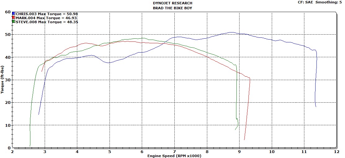
The graph below shows the 400 engine in the SS with the 2 into 1 in red, in the Monster with the original 40mm M600 2 into 2 headers in green and in the Monster with my original header chopped up into kind of crappy 2 into 1 in blue.  Peak power at just over 80mph is 9,500 rpm.  The 400SS top end air/fuel is an issue, and with more main jet it may make more top end power.  The red curve certainly improved a couple with more air to offset its richness.  The midrange air/fuel is similar to the Monster jetting, so comparatively at least should be similarly crappy.


While the original header chopped up into kind of crappy 2 into 1 did give a stronger bottom end (compared to the 2 into 1 of the green curve it has shorter, larger diameter primaries so it's not following the myth there either), it all went pear shaped over 7,500 rpm.  Realistically, that's about as hard as I revved it anyway, so for me it wasn't a big issue.  But the knowledge that I'd made it somewhat worse annoyed me.  I think it's the way I modified the stamped sheet cross over into the 2 into 1 merge, and maybe the fact that it's all the same diameter isn't helping.  But I'm not inclined to find out and that header set only fits a small block Monster with rear sets so it's a bit restricted in application to play with.

Comparison of the two 2 into 1's below, 400SS is blue.  The funny thing is that the 400SS has a real pick up in performance you can feel around 7,000 rpm.  Maybe it's as the fuelling goes from too rich to too lean, dunno.  Definitely noticeable, whereas the Monster with the 2 into 2, which has a much less smooth dyno curve, wasn't.


Torque and air/fuel shows the taper in the 400SS air/fuel curve that I'm sure you can feel as it gets better (before going to shit).


The jetting also varies a bit - they're kind of wacky.  The 350SS and 400SS std jetting variation is bizarre for what is essentially the same bike, produced at the same time.  The jetting I'm using in the 400 is not quite std.  They use a much softer slide spring than anything else - it's almost like a Factory Pro or Dynojet spring.  I did have them in it when it first went together, but swapped the heavier "in everything else" springs into it to make it a bit richer.  Maybe too rich now, not sure.  Everything except the 600SS use larger holes in the slide with the heavier springs too.  Maybe that transfers more vacuum to the diaphragm.

JD Hord made the comment on Facebook that "I did a bunch of messing around with springs on a Honda Hawk one time, and best I could tell, at steady state they had barely any effect, but throttle response did seem slightly better with heavier springs. I suppose that's because it would pull more vacuum and get fuel moving a bit quicker into the airstream."

It did seem to help the throttle response and starting, but I also richened the idle mixture a bit as well.


The 2001 M400 uses the same spec carb as all the M600, so I ran the original M600 carbs on this engine when it was in the Monster.  The jetting is quite different in those two, but the midrange WOT fuelling is similar on the dyno.  I've got a heap more mindless rambling to do on the jetting stuff, watch out for that blog post - it'll be coma inducing.

Sunday, June 28, 2020

Playing with a Ducati fuel level sender

.
I put a post on my Facebook page a while ago about Dcuati parts not being covered by warranty if not fitted by an authorised workshop.  The part that prompted that was a fuel level sender I had purchased for a mid 90's 900SS.  The dealer I bought it from did cover it for me, but that was what they were being told.

Anyway, in that case my customer needed a fuel sender for his 900SS as the light wasn't working.  Shorting the terminals in the loom tank connector made the light come on.  Pretty easy diagnosis.  I ordered one in, fitted it, made sure the light was on with the tank empty then put the fuel back in it and made sure the light went off.  It did.  Bingedy boom, Bob's ya f--king auntie.

As it turned out, Bob was an imposter.  The owner called to say the light wasn't coming on.  He came back, I ran the test again as above - no light.  I ordered another sender and when it arrived it was fitted and job done - I haven't heard of any further issues.

Which meant I had this dud sender on the bench.  The dealer didn't want it back, and I tend to keep all this sort of stuff just because connectors, etc, can be handy.  And I was also convinced that when I had fitted it, I'd checked it properly.  But, as with most things that end up on a bench, it had sat simply because I'd had no need to consider it further.

Until Friday, when the 400SS hit the road.  Although I've owned this bike since 2012, its never been near the road as a bike, and there were a few things about it that I didn't know.  Given how much of a dud it was when I bought it (imagine an Ebayer not telling the whole truth!) I shouldn't have been surprised when I realised on Friday, while heading over to see the club man for the permit papers, that the trip meter wasn't doing anything and that I should have been quite a bit through the 5 litres of fuel I'd put in the dry tank after it was painted.  Enough that the fuel light should be on.  I made a precautionary fill up on the way back and put over 14 litres into it without trying, so it was low.

The sender in the bike would most likely be the original, certainly it's the old design.


The current sender to suit the carby SS, 59210161A, is one of the typical black plastic tubes types with the correct eyelets for the fuel pump terminals and is around $330 locally.  As such, I was pretty keen to not have to buy a new one.  Hence my decision to pick up the alleged dud and see what happened.  I plugged it into the connector, turned the key on and waited the 20 or so seconds for the time delay and the fuel light came on.  Result!  Turned it upside down, heard the float go clonk, light off.  Turned it up the right way again, wait 20 seconds, light back on.  Ok.  So what's wrong with it you might ask?  I certainly did.  I figured I might as well fit it properly and see what happened.

59210161A, image stolen from Belt and Bevel, who allegedly have one in stock.


Short answer - what happened was, it didn't work.  Things started well - the light was on when the tank was empty.  But it didn't go out terribly convincingly when it was covered in fuel.  I usually find these things like some sort of vibration to bring the light on - I often do these tests with the engine running or, if not, tap the tank gently repeatedly.  In this instance, that developed into me going it perhaps a little more aggressively than ideal with a long screw driver handle and eventually the light went out.  As anticipated, it didn't come back on when the fuel was drained again, so out the sender came.

Taking a step that I usually don't with a new "sealed" electrical component that doesn't work, I thought I pull it apart and have a Captain Cook.  Nothing to lose anyway.

The top has a small metallic stud sort of thing on top, which looked to me like it might be solder.  Applying the soldering iron confirmed that, and the solder shook off.  The plastic cap turned out to not be retained by that though, it just clips in and out


The solder retains the little steel top hat that stops the float.  Once the solder was gone, it pulled off with a little twisting with pliers.


Taking the float out, it looked to me like it had some ridges at the ends that were maybe jamming, so I put it in the lathe and tried to machine it a little.  In hindsight, I wouldn't recommend doing that at all.  It looked like something hard, but it sort of powdered when I hit it with the tool and it's also soft and doesn't hold too well.  I made a bit of a mess of it, and then wondered if the outer was some sort of sealing cover that stopped fuel getting into the float's foamy cell.  I guess if it does fill with fuel the light will just stay on.  Note to self time.  Undesired result is below.


Reassembled and refitted again, it delivered a similar result. This time, after the sender was covered with fuel, the light just wouldn't go out.  No amount of tapping, etc, made any difference.  In an attempt to move it around a little, I lifted the front of the tank and noticed a heap of air bubbles coming out the two little holes in the cap.  I found that a little odd, so drained the fuel and removed the sender again - this time keeping it upright hoping what was wrong inside it might not change.  When I popped the little cap out, the float was up and the unit was still full of fuel - an obvious problem.

The reason that's an obvious problem is because there's a hole in the side.  Well, there's meant to be.  Looking at the "hole" in the side a bit harder I realised that the drill hadn't been leant on hard enough.  


Leaning on a 2mm drill a bit harder, I got this:


With that, I reassembled and refitted again with supreme confidence, confidence rewarded with a fuel light going off then coming back on with variations in fuel level.  Woohoo!  Fixed.

Of course, I then re-entered the living hell of getting the fuel cap carrier rubber surround ring back in place.  When I reassembled the tank a couple of weeks ago I finally managed to stretch the rubber enough to get it to stay in place long enough to jam it into the top of the tank.  This time, I gave up and borrowed a pair of hands.  I haven't done that for at least 11 years.

All I have to wait for now is my molested float to fail.
.

Friday, July 5, 2019

Ducati 2V valve clearance, timing belt and cam timing videos

.
Mike Wallis, who does my website, also does video production and runs a Youtube channel called Mike's Machines, so he came in one Saturday and we shot some footage of me banging on while doing a 2V valve clearance adjustment.  Videos here:


.

Wednesday, January 2, 2019

A comparison of 2V and 4V Ducati 750 engines

.
When I did my 2V cam profile measuring (here), I had the chance to test a theory that I had, being that the cam profiles for the 4V Strada cams - marked A1 - were simply the 2V profiles of the time - the F1 cam that became the R grind used in the 600 and 750 engines from 86 to 02.  Turns out I was probably half right.

The inlet profile looks mostly the same.  The exhaust has a fatter nose for want of a better description, and is more asymmetrical, biased to the retarded side.  I found it a bit odd that they would just use the 2V profile, but while in reality the 2V cam was lacking quite a bit of lift when used with the 41mm inlet valve in the 750 F1, its 9.5mm of lift was more than enough for a 32mm inlet valve (as the 748cc 4V initially had).  Lift required is based on the fact that a poppet valve flow area - if you like the curtain you get around the valve od when lifted - is equal to the valve head area when the lift is 1/4 of the valve head diameter.  So if you have 32mm valve you need 8mm lift.  And 41mm needs 10.25mm lift.  It's a rough guide sort of thing.  By the time they got to the production 748, the inlet valves had grown to 33mm and exhausts to 29mm.

(Thinking back to the above now, after having written much of what follows, I've come to the conclusion that this comparison is flawed from the start.  The 750F1 cam simply doesn't have enough lift for its valves.  Maybe someone on the 4V project at Ducati (Bordi and his team) saw the profile and thought "That's about right for a 32mm valve, I'll have that".  Fair play to them.)

(And another - the 85 750F1 has small 500 Pantah valve sizes, so maybe for them the valve lift was ok.)

To the profile comparison.  Blue and red are A1 inlet and exhaust, green and orange the R inlet and exhaust.


I then wondered if they'd used the P grind from the hot F1 series - Montjuich, Laguna Seca and Santamonica - for the A cam used in the 851 Tricolore Kit and SP series.  But clearly not, the P has much more lift and more duration.

Some time later it occured to me that this meant there were a couple of engines from the same manufacturer with the same bore and stroke using the same inlet cam profile and a similar exhaust cam profile in both 2V and 4V configurations.  Those two engines are the 750 2V and 748 4V, both with bore and stroke of 88 x 61.5mm.

As such, I thought a comparison of 2V and 4V was in order.

In basic engine design, the potential peak torque value is based predominantly on capacity.  There is a measure called Brake Mean Effective Pressure, which is basically torque per cc, and it's somewhat consistant with similar engine designs and a measure of efficiency, both volumetric (how much air the engine can suck in and then trap) and combustion (compression ratio, chamber design).  The actual outright potential efficiency in terms of energy in versus power out is related to the compression ratio, although measures to reduce losses are a big part of engine design these days.

In contrast, the potential peak power value is not capacity based, but air flow based.  Simply, how much air can the engine flow through itself.  This also overlaps with mechanical design and maximum rpm potential.  If you're designing an engine for racing, for instance, you'd start by defining the maximum rpm you're going to use, which is mostly bound by piston speed.  Maximum piston speed is not an enforced limit, but a number that is in reality a development boundary to be pushed and see what happens.  The old "to finish first, one must first finish" kind of thing.  Usually defined as "mean piston speed", which is the average speed over the journey from top to bottom.  The actual maximum piston speed, which occurs about mid stroke, also varies with connecting rod length.  Seems that 30m/s is about the current maximum "mean" used.

With the limits of capacity and maximum piston speed set, the stroke is defined and then the bore defined by that.  Or, in MotoGP for instance, where the capacity limit is 1000cc and bore limit 81mm, those limits give a minimum stroke of 48.5mm, which in turn, if the maximum rpm used is 17,000, gives a minimum mean piston speed of 27.5m/s.

This can also depend on physical properties of components used too, and the limit there, if not specified by rules, is generally cost.  The old "how fast do you want to spend".  As a guide, when Ducati were at the end of the 999 race life, they were revving them to 14,500rpm to try to be competitive.  With a 63.5mm stroke, that gives a mean piston speed of 30.7m/s.  Pistons and connecting rods were not limited by the rules, though, unlike the 1198 era when production parts had to be used.  Through material spec and cost, this effectively limits the maximum mean piston speed indirectly.  This, along with the physical limit of further enlargement of bore size on the Pantah derived 1198 crankcases, is what led to the Panigale engine development.  Bigger bore means shorter stroke, and the shorter stroke was what they needed at the time.

The main secondary variation in terms of possible peak torque production is that the 4V engine has more compression, which realistically is 1/ simply a by product of the required (and better) pent roof combustion chamber design, and 2/ also permitted by that same chamber design with its ability to better resist detonation - ie, a smaller, shallower chamber with valves at a much smaller included angle, large squish areas and a central spark plug.  It is also water cooled, again making it a better high performance engine.  So the generic 4V pent roof head configuration has combustion chamber design advantages you can't get in a 2V without restricting valve size markedly.  The 2V chamber in the 750 engine is a (largely) hemispherical type chamber, which tends to give a deep chamber with much more valve angle than the 4V design simply to get the required valves in.  If you want high compression, you use a piston with a dome that in itself causes issues with flame front travel and increases the potential for detonation.

In so many ways the shallower 4V chamber and flat top piston are just better.

748 chamber on the left, 750 on the right.  748 valve sizes are 33/29mm inlet/exhaust, the 750 is one of my bigger valve heads with 42.5/37mm.  Std 750 is 41/35mm.


Comparing power and torque outputs was the aim of this, so we'll get into it.  Blue is 748, red 750SS and green 750SSie.


The power graph shows the 748 peak power value around 50% more than the 750, at an rpm similarly 50% higher.  This makes sense, as power is defined as torque x rpm.  Same torque at 50% higher rpm will give 50% more power.  If you compare the valve sizes, the 748 has about 30% more valve area.


The torque output, on the other hand, shows some of the implications of trying to spread the rpm range over which the power is produced.  The 2V curves are both generally just rounded curves, whereas the 748 has various peaks and troughs.  This is usually what happens as you widen the rpm range you're tuning for.  At lower rpm, as a general rule, you want things to be longer.

The difference between the 750SS and 750SSie is carburettors vs fuel injection.  The 750 engine with the Mikuni carbs has long inlet manifolds that position the carbs side by side.  The 750 ie engine has much shorter manifolds and throttle bodies arranged at 90 to each other, giving the appearance of a much shorter inlet tract.  In reality, the carb model has short rubbers into the airbox, whereas the ie model has much longer rubber trumpets inside the airbox (much longer on the vertical cylinder) that would mean the overall trumpet to port dimension would not be that much different between the two models.  Keep in mind everything else engine wise - heads, valves, pistons, cams - are the exact same parts.

One thing that is done when you try to extend the power range is to make the inlet shorter.  This helps the overall peak power value, but while it also reduces the peak torque value, it will increase the average torque figure over the wider rpm range and introduce the peaks and troughs.  The narrower the rpm you tune for, the more specific you can be in your tuning setup - inlet length, etc, and that will lead to a higher peak torque figure.  Great for a unique application such as a stationary engine, not so good for general motorcycle use.

There is a great dyno graph that I have never been able to find online - the only place I can recall seeing it in Sir Harry Ricardo's book - from D type Jaguar testing that shows the power curve with inlet lengths varying from maybe 6 to 36 inches.  At 36" the peak torque is well above that of 6", but the rpm range is much narrower.  As an implications and compromises of tuning illustration, it's particularly simple, elegant and quite definitive.  I might have to go to a Uni library and photocopy it some day.

Another point here is that while the inlet cams in this instance are all spec'd at the same timing - 119 degrees inlet centreline, with the exhausts at 106 on the 2V and 112 on the 4V, in reality the 2V would be pretty close to that or even maybe 1 or 2 degrees advanced, whereas the 4V would have all cams retarded to some extent.  We used to find 4V inlets from 5 to 10 degrees retarded out of the box, and when we reset the timing to 108/108 we did sometimes move inlet cams over 20 degrees.  This gives a better shape to the 748 torque curve, as below.  Blue is as delivered, red 108/108.


Incidentally, when this cam first appeared in the 750F1, the timing was 10 degrees more advanced than in the 750 Paso, which makes much more sense to me.  I have read that the timing was changed for "emissions" reasons, which really makes no sense to me as there was no motorcycle emissions testing back then.  I'd speculate it was done for two reasons.

1/ The Paso, with the longer inlet manifolds and Weber carb, had a more midrange orientated power delivery, and retarding the cam timing gave a power delivery more in keeping with what was expected and helped increase the outright power figure.

2/ With the fully enclosed body of the Paso and a compression ratio much the same as the F1 (spec is 10:1 in the Paso manual), even with the oil cooling system I'd think the risk of detonation would have been higher so retarding the cam timing would reduce the midrange cylinder pressure.

By the time the 750SS appeared it had pistons which are the slightest bulge off flat, and the listed compression ratio of 9:1 meant that there was no detonation in sight.  The other difference with the later pistons was that the inlet valve reflief was shallower, so the most advanced I was game to run those cams was 114 degree inlet centreline.  Not sure if you could run 110 on a 750 Paso or not.

Comparing a 750SS with timing at 119 and 114 we get the following.  If we could have run 110 and picked up a little more at the 5500 rpm torque peak and lost a little more over 8000 rpm it would definitely impact the feel of the power delivery, and that may have been a bad thing when you only have 2V motors on offer and people who just love pointlessly revving the snot out of things.


Inevitably, the two previous graphs lead to this one, being 748 vs 750 with more consistant cam timing settings.


Peak torque is almost the same, peak power about the same difference as before.


Yeah, but.....

Frankly, there's more yebits to this story than story.  It was sort of a good idea that has, realistically, taken it in the neck quite a few times along the way.

One could argue that we could make the 750 engine a better one for this comparison by giving it a different cam with more appropriate lift.  Totally negating the comparison, of course.  And its under valved, so lets fix that too.  And the comp is too low compared to the 748.  Luckily, I prepared one earlier.  My 750 engine with 900 cams, 42.5/37 valves and Ferracci 12:1 pistons.  The 900 cams have 12 degrees more duration and 2.5mm more lift.


Even though the cam duration has gone up, the torque curve is still a single peak, typical of the 2V motors.  

But, if we're going to make the 750 a bit better, we can make the 748 better too.  Along the way they had a couple of goes at the 748.  The SP/SPS with its great big old school cams, and the R with the bigger throttles and valves and half big cams.  Neither made a better road bike - it always dismayed me when people who bought 748R came in and claimed their old 748 had more midrange.  Of course it did.  The concept of an homologation special is not understood by many.

748 in blue, 748SPS in green, 748R in red.  Different shape curves, or more importantly, different amounts of torque over 10,000rpm.  Where the power is.  But, the peak torque value is pretty consistant across the 3, as it has been for all the graphs so far.


But (I'm liking these buts), if we're going to improve the 750, we might as well improve the 748 too.  Properly.  That involves bigger valves again - 37/30.5, larger than the 748/748SP at 33/29 or the 748R's 36/30, but reduced cam duration - at least 20 degrees on the inlet and 16 on the exhaust with appropriate lift.  Let's call it a 749.

The totally different exhaust designs may influence the 749 output, but in comparison to the above 748's adding a base model 749 curve in burgundy shows how much better it is.  Again, 750cc so similar peak torque, but the shorter cam duration and bigger valves combine to give better low rpm and high rpm torque compared to the 748.  The valve of good heads and just enough cam.  Although, on the road, it's kind of a boring power delivery.  Having the torque rise more noticeably with the rpm does make them feel more racy.


Power curves show the 749 is much more linear.  I think it'd make a good naked bike motor.


I might stop there.  I've kind of lost the direction of this, which really is just me thinking about it too much.


Friday, December 28, 2018

Closing rocker spring change on the 851.

.
One thing about the 851 that has annoyed me for many years is the way it idles - best described as crap.  As a 1989 model it has the early soft closing springs - the springs used to (try to) keep the valves closed as per #5 the picture below.  They're not valve springs in the typical sense, just a helper.


If you run the engine without them, they tend not to idle very well.  Once the revs are up it's not an issue, but at idle too much cylinder pressure leaks past the valve seats.  In use that translates to a lot of misfiring and oxygen and hydrocarbons in the exhaust mixture, which makes it unpleasant to be behind.  Even with the soft "Corsa" springs as this bike had they're not a lot better.

I had hoped that adjusting the valve clearances would fix the issue.  When I first purchased the bike I had given it a big service, adjusting the valve clearances and replacing the original stainless steel collets with steel ones.  The new collets tend to settle (wear) into the shims and valves, so you always need to adjust again once that has happened.  Over the 6,000km I had ridden it in the 3 or so years I had it on the road it had become slowly worse, and parking it for 13 years was the most simple solution.

During the "back on the road" service recently I had found a lot of clearance - most around the 0.20mm range - and 3 pairs of broken collets. Once adjusted though, it wasn't a lot better, still having a fairly ropey idle with a dirty mixture - lots of O2 and HC to really get up your nose.  And that was probably the thing that was annoying me the most now - being embarrassed at how horrible it would have been to be around the bike while sitting idling at traffic lights, etc.

I recall servicing an early 851 years ago at Moto One, pulling the closing clearances down nice and tight and it was nice and clean at idle, so was hoping for a similar result again.  Not to be, unfortunately.  To give you an idea, this is what a dirty mixture looks like on the gas analyser.  5000ppm HC and 5% O2 makes for runny eyes.


I had come to the conclusion the fix was the heavier closing springs fitted from 1991 models onwards.  Confirmation of this came from the early ST3, which had a recall involving replacing the exhaust rocker closing spring with a much heavier part.  The very soft inlet springs stayed as they were, and it took them from having a mixture like the above to the expected clean.

All the later model 4V Strada cam bikes tend to idle very nicely, and I could see no reason why my 851 should be any worse.  It had good leakdown and cranking compression, both of which would indicate satisfactory general health.  And there wasn't a great deal of wobble in the valve guides.

Ideally, I would have pulled the cylinders and heads and fitted the new pair of cylinders and pistons I have, along with 748 heads modified as per the 853 kit procedure and fitted with the heavy springs.  Would have been an absolute treat.  But, I'm not really interested in that sort of thing these days - really, I just want a bike to be able to ride, and the 851 was the only complete, club reg eligible bike I had available at the time.  The time investment required is more than I have available to spend.

The only other option was to swap the closing springs with the heads in place.  I wasn't looking forward to it.  There's a French fellow named Patrick who did his years ago and has been encouraging me to do the same via the 851 forum, but I was still reluctant.  Until the last time I rode it and decided I'd had enough.

So I dug the set of springs I've had for 15 or so years out of the tub and put the bike on the bench.  Everything externally removable has to come out of the heads, as below.  That's the easy bit.


You can see the difference in the springs clearly in a side by side photo.  The original are 2.0mm wire diameter with 7 coils.  The replacements are 2.7mm wire diameter with 5 coils.  Using the spring rate calculator I usually use for fork springs (I think it'd work for rotating coils) and guessing the coil diameter at 15mm give rates of 1.0 and 5.5 kg/mm.  Not sure that I believe that, but the spring rate is proportional to the wire diameter to the power of 4 and inversely to the number of coils.  Thicker wire and less coils both give a higher rate.  In terms of how hard it is to push the rocker down, there's a significant difference.  Let's go with that.


The worst part of the replacement procedure, as it turns out, was getting the springs and rockers back into place and the pins in.  The closing rockers and pins are at the very outer corners of the above photo, and getting in there with limited access - vertical exhaust and both sides of the horizontal with the radiator still in place (frankly, I've had the f#*%ing radiator out of this thing so many times in the last few months that it was not coming out again.  Funny the jobs you absolutely hate) and with everything coated in Motul 300V it was as slippery as the proverbial two eels in a bucket of snot.  I resorted to zip tying the springs in and then poking the rockers in.  There was a fair amount of cussing - you work blue with this kind of job.


I started on the vertical, as I figured the exhausts would be the worst.  As a clarification as to why this is a crap job, the tail of the spring has to go under a lug cast into the inside of the head.  In the above photo, the lug is between the two closing rocker pins - the tails go under one from each side.  The spring tail is behind the zip tie, so you have to pull it down maybe 70 degrees.  It's not a fun job, even when the head is on the bench.  But my home made tool can work an absolute treat.

Speaking of my home made tool, I used it last week on an ST4S head, the frustration of which reminded me after the fact that I was using it wrong.  You'd think I'd remember how to use my own tool.  Ideally, this tool works best from the opposite side - you work the exhaust spring tail under the lug from the inlet side.  There's no access from the vertical exhaust side, so I popped the inlet spring in first from the inlet side then tried the exhaust.  The first one went in so easily it could only give me a false sense of success.  Working around the radiator and thermo fan on the horizontal sucked.  But, overall, it wasn't as bad as I was fearing.

The tool.


Then it was just a case of putting everything back in, and then everything back on (replaced what looked like a leaky timing shaft seal too) and it was time to fire it up and see what happened.  It was a satisfying pile of debris once done.


When I had the plugs out I noticed the vertical was whiter than the horizontal, so I adjusted the throttle linkage rose joints out of alignment to close the vertical throttle blade a little.  I couldn't be bothered doing it properly, it's such a pain access wise with it assembled to a run-able state.  As I hoped, it was idling higher.  At least that was reassuring, the valves were holding compression better.  I didn't replace the eprom first as I had planned, and to my surprise it was a lot leaner than it had been previously.  I guess the holding compression relates directly to trapping more air.  I wound the idle trimmer on the ecu a couple of turns counter clockwise to richen the mixture, and we went from around 1% CO to 4% CO.  It wasn't a lot cleaner mixture wise than it had been previously - it's in the 2500 - 3000ppm HC and 2.5 - 3.5% O2 range around 4% CO, but it idled so much lower and smoother that it was clearly better.

For an eprom I compared the 009B based eprom I was running with the 035 eprom from the 1992 851.  The 89 - 91 bikes all used the 009/009B - the B refers to a software change that Duane told me related to how the engine was "turned off", which was done to improve the life of the starter clutches.  It was done well before my time, and I've never found a service bulletin relating to it.

The 1991 model used the heavy closing springs with the 009B eprom, but I don't recall how they ran.  Don't know if I've ever ridden a 91 now that I think about it.

Comparing the 009B to the 035 gives the % differences as below.  Negative numbers mean 035 is leaner.  Blue along the bottom is RPM, red up the side is throttle opening in degrees.  P7 ecu starts at 0 degrees, which is the lowest TPS output voltage it sees every time the key is turned on.  It's not actual throttle opening, just opening from closed.  The implication here is that if you change the closed throttle position on the idle stop you change the fueling at low throttle openings.  Can be a frustrating system, as the only way to adjust idle speed is with the idle stops as the P7 throttle bodies have no air bleeds.


The 035 eprom is a lot leaner at low throttle than the 009B, and that is the direction I was heading with the eprom I had been running which was my mapping from when I was using an Ultimap UM011 based eprom dropped over the 009B base software with some changes to the environmental trims.  The 009B is also richer on the air temp trims, so in use it will be richer than the above comparison indicates.  I leaned those trims off and reduced the range of them in the eprom I'm running now.

Comparing my eprom to the 035 is as below.  The temp trims on them are much closer.  I made the lower throttle lines the same as the 035 pretty much, and the 035 idle fuel was spot on with the idle trimmer set to the mid point - you remove the top of the ecu and measure the voltage at the trim pot outputs and set them to 2.5V, which is midway between 0 and 5 (oddly enough).  I like to start at the mid point if I can.


The larger positive differences at the top up to 7,000 rpm are for the revised cam timing - closing the inlets earlier traps more air and needs more fuel.  Although after the torque peak, you need less fuel as the volumetric efficiency is dropping faster.  So 8,000 rpm and up it's getting less fuel.  I have the rev limiter set to just under 10,000 rpm from memory, so the point at 10,500 is redundant.

The -100 on the bottom line is simply due to me turning the fuel off on overrun.  You just make the map value 0.

After all this I put it back together and went for a ride.  It was pretty hot here today - 37 degrees - and that may influence how it ran a touch.  Possibly influenced how it started too.  When I turned it on the temp gauge moved off the stop even though the engine was "cold".  I have made the coolant trims at 5 and 17 degrees coolant temp richer from memory, but once running it doesn't need more enrichment as it warms up through the 29 and 41 degree points.  But they do like more fuel for the initial start, and the ecu from 1.6M onwards have a starting enrichment table as well as a coolant trim table, where they have a decaying enrichment that works on rotations since started.

It almost gave me the impression it was a little off a few times, but the more I rode it the harder it was to find any proof of that.  It had a point at 3,500 rpm just off closed throttle that may be too lean, as it shuts down a little there at times, but it's not really an issue.  It really is a lot nicer at low throttle openings, which was the point of this.

I was going to check the idle mixture after riding it in case it'd cleaned up a bit more due to valves seating better with a run, but forgot.

It did cut out a few times as I pulled the clutch in coming to a stop.  Usually that's ignition timing based, but this eprom has modifed spark map breaks that allow more advance at 1000 rpm to try to stop that, and a plateau from 1100 to 1500 that gives you good control of the idle speed with the advance at those points being the same as the original eprom value - 6 degrees from memory.  But I may put some more advance in - it makes them idle nicer if you can add advance without losing control of the idle speed.  That part is annoying as I've never had this bike do that before, and it's another reason to have to remove the seat base to get to the ecu.  Usually more than once.  I'm so over replacing eproms - flashing ecu is so much easier.


And I think the clutch might be slipping.  I'll see how long I can ignore it for.