.
I've put up a new report about Moto Guzzi Daytona RS and have also moved some blog posts over to proper reports, such as the Throttle Position Sensor setting procedure for California and Bellagio and Tuning an 851 SP. Or, the things you don’t know you don’t know..
Also, at the start of appropriate sections, I've added a "collected blog posts" report to link all the blog posts. So that way you don't need to scroll through all the blog posts to try to find stuff that applies to what you're looking for.
For example, at the start of the Ducati 2 Valve section there's 2V Ducati fitted with Keihin FCR carbs - Collected blog posts
.
Saturday, August 17, 2013

Wednesday, July 10, 2013
Mounting pod filters on a Ducati 4V intake
.
Some time ago I tuned an 888 fitted with a hot 955cc SP5 style motor. One of the changes was some throttle bodies bored to 54mm. Amongst other agro, I found the air filter was sitting on the (oversized carbon) horizontal cylinder inlet trumpet. So I suggested to the owner that maybe fitting some pod filters over the trumpets could be a good idea.
To mount the trumpets I used some muffler end caps sourced from a local exhaust manufacturer. These had (from memory) an ID of around 58mm and an OD of 100, over which I fitted some K&N RC-5057 filters. Actually, now that I look at the photos, maybe the OD was smaller and I fitted some aluminium tube to bring the OD up to 100mm. I forget now.
Photos below show the fitment. I cut the front out of the airbox, so from the sides it look std. Due to further agro with the 54mm throttle bodies it ended up having std SP5 throttle bodies fitted, so the whole exercise was a little moot in the end. Not sure if it helped or not.
But the main reason I'm posting photos is for a fellow on the Monster forum, who want's to put pods on an S4 Monster. I would always recommend keeping the trumpets in this instance. Removing the trumpets and fitting pods direct to the throttle bodies never seems to work well.
The reason there is a space under the trumpet mount above the throttle body is that the 888 airbox is held on by sitting between the trumpet and the throttle bodies, unlike the later bikes where the trumpets twist and lock into the throttle bodies and the airbox is frame mounted.
Monday, July 8, 2013
Ducati 2V cam comparison: pre 2002 3 bearing cams vs 2002 on two bearing cam
.
Someone asked me about fitting 800 cams into a 750 motor, so given I have 620 and 750 cams easily at hand I figured I'd take a photo and make it a bit clearer.
Prior to the 620 and 800 motors being introduced, all the cams since Pantah run with two bearings at the pulley end and one in the cap. Part of the 620 and 800 minor redo was to drop one of the pulley end bearings. The cap end is also different, with about 3 or 4mm added. The form is the same, it's just longer.
To fit a 3 bearing cam into a 2 bearing motor you just need some spacers to position the cam correctly at the pulley end, as the cam is pulled to the pulley end when tightened.
But to fit a 2 bearing cam into a 3 bearing head you need to grind the cam to locate the larger, inner bearing at the pulley end (as it sits next to the lobe) and also shorten both the snout and spacer section at the cap end. I don't think you could just add another bearing further in at the pulley end, as the head is machined to locate the outer bearing in its position. I think, I'd have to look now that I'm saying it to remind myself.
Anyway, photo below. 750 at front, 620 at rear.

.
Saturday, July 6, 2013
Tuning an 851 SP. Or, the things you don’t know you don’t know.
.
 The main point here is that the top line (WOT) you can see FF at 8,000
rpm, along with FA at 7,000 and FC at 9,000.
This means that the biggest number available is being used. However, to clarify a point, this is not the
same thing as duty cycle. Duty cycle is
the time the injectors are open expressed as a % of the total time available to
open them. The dual injector throttle body report deals with this more. Going from FA to
FF is only a 2.4% change, so there’s not much more at all available over the
range in which the torque peaks.
What FF means is that the software can’t have a longer pulse width on the fuel map. In the case of the Weber systems, FF means 17 milliseconds. Why 17ms I don’t know, but that’s what it is. And each increment is 17/255 or 0.0667ms.
In the case of the dual injector P7 and P8 bikes, once the pulse width duration goes over a certain time as defined in the software, the duration is cut in half and the second injector is opened as well. Meaning each injector can be opened for a maximum of 8.5ms. If you have a look at the dual injector report you can see the implications and benefits of that.
But, the issue the FF brings in this case is that, with std mufflers, etc, the SP2/3/4 is already using the maximum amount of fuel per cycle at the torque peak. Meaning that when you open it up and decide you need more fuel, you can’t have any. So, by definition, any std dual (black or red) injector, A cammed 851 kit to SP4 will be lean around 7 to 9,000 rpm. As an aside, the 851SP of 1989 ran single green IW031 injectors, and would be fine.
How do you get around this? Well, there are two obvious ways, and two not so:
1. Fit larger injectors.
2. Increase fuel pressure (ala race kit).
3. Offset environmental trims.
4. Fit an add on unit like a PC3, Bazzaz, Dobeck.
Why option 1 was never acted on until the change of throttle body design with the 888 I don’t know. It’s obvious, as it was from the start: the 851Kit fuel map has FE on it. And they were fitting the larger IW031 green injectors to the 1989 851 and later 907.
Option 2 was the route taken for the 851 Kit, and the race prep notes mention the 5 bar fuel pressure regulator and possibly also the special (read ‘it’s expensive because it’s race’) fuel pump to knock it out for long periods. The road bikes run 3 bar, increasing to 3.5 bar gives you 8% more fuel, 4 bar gives you 15.5%. But, you don’t need the blanket change that a fuel pressure increase gives you, you just need more in a certain range. Although for many, especially back in the day when tuning options and knowhow were very limited, bumping up the fuel pressure would have worked just fine.
Option 3 I can’t confirm, but from what Duane Mitchell explained to me some time ago it should work. Those familiar with 851 are most likely aware of the 008 and 009 eproms. 008 is for open airbox lid and std mufflers with baffles removed. 009 is for all std. The difference is 6%, and is achieved not by richening the fuel map, but by increasing the ambient air temp trims by 6%. This blanket change is much the same as increasing the fuel pressure from 3 to 3.4 bar. Not very precise, but the 008 does seem to work quite well. Of course, if you set the idle mixture via the idle trimmer with the 008, you will reduce the lower throttle enrichment considerably.
The further implication of option 3 is that you can use the environmental trims to overcome the FF issue. This is why adding fuel via the FIM hand held terminal worked on the dyno. The hand held terminal’s input to the pulse width is added well down the calculation stream, and the 17ms restriction is only on the actual map number. So I believe what was initially 17ms can be trimmed up to (theoretically) the maximum allowed by the cycle time once the pulse width calculations begin for any given cycle.
The graph below shows the air/fuel ratio for the SP4 I ran back in August 2001, the first time I had used the Dynojet air/fuel ratio set up. And, in hindsight, there was a very obvious reason why it confused me enough to pull the sensor tube out of the muffler after my first attempt at putting changes into the additional memory board. I wish I hadn’t now. But, anyway, blue is the base fuelling on the eprom fitted to that bike (BMM01), which I now know had FF at 6,500, 7,000, 8,000 and 9,000 rpm. Red is with +10 via the hand held terminal. Clearly, it’s a consistent +10 change across the range, so the hand held terminal is able to do what an eprom can’t.


While the engine temp trims are as expected, and with the engine being water cooled, relatively stable and inert during use, the ambient air trims are a problem. You can see that at 17 degrees, the correction is +3.1%. At 29 degrees, it’s -3.1% and at 41 degrees it’s -6.3%. As it turns out, these corrections are chemically correct for the change in air density due to temperature. But, as ever, it’s the theory versus application thing that brings us undone.
If the bike is stationary or moving at low speed and hot, a lot of radiated heat comes up into the airbox. Where is the ambient air temp sensor on an 851 and 888? In the airbox. So it will read the radiated heat and act on it. If you pull up at a set of lights on a 17 degree day, by the time you take off again a couple of minutes later the airbox temp may certainly have hit 41 degrees or higher. In which case, your fuelling when you take off will be 9.4% leaner than it was when you pulled up. Once the bike is moving the airbox temp will quickly drop again, but by that point you’ll have stumbled or stalled and grabbed a handful of throttle to get the thing going and before you know it you’ve got a reputation for not liking traffic.
The 008 and 009 eproms don’t have this variation in ambient air temp trims (they have 3.1%), so I don’t know why it shows up on the SP eproms. I moved my 851 air temp sensor from the airbox to up behind the LHF indicator, which helped, but didn’t totally eliminate the issue when using an eprom with the SP based ambient air temp trim table.
And, finally, we get to applying all the above. I had an SP4 in recently which was running a bit odd after a restoration and also stalling. During the resto it have been found that two of the injectors were dodgy, but they had been replaced with the green IW031 injectors as found on the 1989 on 851 Strada, 907 and 750/900SSie, not the red (IW042). I supplied another pair of greens to make them all green, and on the injector cleaning company’s test bench the reds flowed 40 (of whatever units) and the greens 65 from memory. So the greens flow quite a lot more.
I also went through the valve clearances, tightening the closing clearances and reset the cam timing to 98/102 centrelines.
With all the above in mind, I made a revised eprom with changes to the fuel (guessed) and spark mapping and the ambient air temp trims and then ran it on the dyno and road and adjusted the fuelling as required. The fuel changes weren’t a blanket offset, and there’s definitely less change on the WOT line from 6,500 to 8,000 rpm. The changes to the fuel mapping are shown below.

The first time I played with an 851 SP (SP3), I ran it on the dyno then
had Duane make me an eprom as required.
But, it didn’t seem to work as I anticipated it would.
Next time it was an SP4, fitted with an FIM additional memory board in
the P7 ecu. Although I made many changes
across the fuel mapping, and generally made the low speed running much nicer,
the WOT fuelling didn’t change as I had expected. Specifically, when I made zoned fuelling
changes with the FIM hand held terminal the air/fuel ratio changed as
expected. But with the changes converted
to actual mapping with the additional memory board (too much to explain), the
air/fuel ratio didn’t change in some places.
Sometime later, when I had software to look at the fuel and associated maps
themselves, I noticed a couple of things that explained much of this. And introduced me to a concept I now
appreciate well: it’s what you don’t know you don’t know that brings you undone.
First up, the fuel map on the SP2/3/4 shows the first issue. Some background: the SP was the hot one, with
the flash “race” bits such as dual injectors with staged operation. This feature in particular really peaked
people’s interest and really helped build the folklore. Unfortunately, it didn’t quite work as
expected, both literally and mythically.
As introduced on the 1988 851 Strada and Kit, the black or red (IW042) dual
injectors were used up to SP4. The same
injectors were used on the factory race bikes (Lucchinelli and Roche Replicas,
etc), but with the fuel pressure raised to 5 bar from the std 3 bar. Which made complete sense once I’d seen the
fuel map. Incidentally, the P7 ecu only
has one fuel map, not main and offset like the P8 and later ecus.
Below is the fuel map from the 888 SP4 037 eprom, in hexadecimal form. For those unfamiliar with hexadecimal, it is a
number system with a base of 16, not 10.
Like decimal, it has 0 to 9, but then above 9 there is A to F. In 8 bit hexadecimal, you get a pair of
digits for each number giving a total of 256 numbers. But, you need to remember that 0 is a number,
so the range is 0 to 255. Like decimal
is base 10, with a range of 0 to 9. So
00 is 0, 10 is 16 and FF is 255. The
fuel maps in P7, P8, 1.6M and 1.5M are all 8 bit, although the rpm values are
16 bit on all from memory, meaning they are made up of two pairs, such as
3F4A. The maps in the later 5.9M and 5AM
on are 16 bit as well, giving a maximum map number of FFFF, or 65535. The red numbers at the RH side are degrees of
throttle opening, the blue number along the bottom rpm x 100.

What FF means is that the software can’t have a longer pulse width on the fuel map. In the case of the Weber systems, FF means 17 milliseconds. Why 17ms I don’t know, but that’s what it is. And each increment is 17/255 or 0.0667ms.
In the case of the dual injector P7 and P8 bikes, once the pulse width duration goes over a certain time as defined in the software, the duration is cut in half and the second injector is opened as well. Meaning each injector can be opened for a maximum of 8.5ms. If you have a look at the dual injector report you can see the implications and benefits of that.
But, the issue the FF brings in this case is that, with std mufflers, etc, the SP2/3/4 is already using the maximum amount of fuel per cycle at the torque peak. Meaning that when you open it up and decide you need more fuel, you can’t have any. So, by definition, any std dual (black or red) injector, A cammed 851 kit to SP4 will be lean around 7 to 9,000 rpm. As an aside, the 851SP of 1989 ran single green IW031 injectors, and would be fine.
How do you get around this? Well, there are two obvious ways, and two not so:
1. Fit larger injectors.
2. Increase fuel pressure (ala race kit).
3. Offset environmental trims.
4. Fit an add on unit like a PC3, Bazzaz, Dobeck.
Why option 1 was never acted on until the change of throttle body design with the 888 I don’t know. It’s obvious, as it was from the start: the 851Kit fuel map has FE on it. And they were fitting the larger IW031 green injectors to the 1989 851 and later 907.
Option 2 was the route taken for the 851 Kit, and the race prep notes mention the 5 bar fuel pressure regulator and possibly also the special (read ‘it’s expensive because it’s race’) fuel pump to knock it out for long periods. The road bikes run 3 bar, increasing to 3.5 bar gives you 8% more fuel, 4 bar gives you 15.5%. But, you don’t need the blanket change that a fuel pressure increase gives you, you just need more in a certain range. Although for many, especially back in the day when tuning options and knowhow were very limited, bumping up the fuel pressure would have worked just fine.
Option 3 I can’t confirm, but from what Duane Mitchell explained to me some time ago it should work. Those familiar with 851 are most likely aware of the 008 and 009 eproms. 008 is for open airbox lid and std mufflers with baffles removed. 009 is for all std. The difference is 6%, and is achieved not by richening the fuel map, but by increasing the ambient air temp trims by 6%. This blanket change is much the same as increasing the fuel pressure from 3 to 3.4 bar. Not very precise, but the 008 does seem to work quite well. Of course, if you set the idle mixture via the idle trimmer with the 008, you will reduce the lower throttle enrichment considerably.
The further implication of option 3 is that you can use the environmental trims to overcome the FF issue. This is why adding fuel via the FIM hand held terminal worked on the dyno. The hand held terminal’s input to the pulse width is added well down the calculation stream, and the 17ms restriction is only on the actual map number. So I believe what was initially 17ms can be trimmed up to (theoretically) the maximum allowed by the cycle time once the pulse width calculations begin for any given cycle.
The graph below shows the air/fuel ratio for the SP4 I ran back in August 2001, the first time I had used the Dynojet air/fuel ratio set up. And, in hindsight, there was a very obvious reason why it confused me enough to pull the sensor tube out of the muffler after my first attempt at putting changes into the additional memory board. I wish I hadn’t now. But, anyway, blue is the base fuelling on the eprom fitted to that bike (BMM01), which I now know had FF at 6,500, 7,000, 8,000 and 9,000 rpm. Red is with +10 via the hand held terminal. Clearly, it’s a consistent +10 change across the range, so the hand held terminal is able to do what an eprom can’t.

Option 4 is simply because there is more time available (much more), so
even though the PC3, etc, can only be connected to one of the two injectors per
cylinder, it will help. The point is
that not a lot more fuel is needed, but it’s enough to be a bit of an issue.
Moving on, the environmental trim tables throw up some more issues
though. The SP3 ambient air and engine
temperature trim tables are show below.

While the engine temp trims are as expected, and with the engine being water cooled, relatively stable and inert during use, the ambient air trims are a problem. You can see that at 17 degrees, the correction is +3.1%. At 29 degrees, it’s -3.1% and at 41 degrees it’s -6.3%. As it turns out, these corrections are chemically correct for the change in air density due to temperature. But, as ever, it’s the theory versus application thing that brings us undone.
If the bike is stationary or moving at low speed and hot, a lot of radiated heat comes up into the airbox. Where is the ambient air temp sensor on an 851 and 888? In the airbox. So it will read the radiated heat and act on it. If you pull up at a set of lights on a 17 degree day, by the time you take off again a couple of minutes later the airbox temp may certainly have hit 41 degrees or higher. In which case, your fuelling when you take off will be 9.4% leaner than it was when you pulled up. Once the bike is moving the airbox temp will quickly drop again, but by that point you’ll have stumbled or stalled and grabbed a handful of throttle to get the thing going and before you know it you’ve got a reputation for not liking traffic.
The 008 and 009 eproms don’t have this variation in ambient air temp trims (they have 3.1%), so I don’t know why it shows up on the SP eproms. I moved my 851 air temp sensor from the airbox to up behind the LHF indicator, which helped, but didn’t totally eliminate the issue when using an eprom with the SP based ambient air temp trim table.
And, finally, we get to applying all the above. I had an SP4 in recently which was running a bit odd after a restoration and also stalling. During the resto it have been found that two of the injectors were dodgy, but they had been replaced with the green IW031 injectors as found on the 1989 on 851 Strada, 907 and 750/900SSie, not the red (IW042). I supplied another pair of greens to make them all green, and on the injector cleaning company’s test bench the reds flowed 40 (of whatever units) and the greens 65 from memory. So the greens flow quite a lot more.
I also went through the valve clearances, tightening the closing clearances and reset the cam timing to 98/102 centrelines.
With all the above in mind, I made a revised eprom with changes to the fuel (guessed) and spark mapping and the ambient air temp trims and then ran it on the dyno and road and adjusted the fuelling as required. The fuel changes weren’t a blanket offset, and there’s definitely less change on the WOT line from 6,500 to 8,000 rpm. The changes to the fuel mapping are shown below.

The changes I made to the spark advance mapping weren’t just dyno power
related. The eproms for the Kit and SP
motors have a lot of advance at low rpm and throttle to try to overcome the cam
duration, up to 59 degrees at 2,500 rpm and above. But at idle they drop to 10 degrees, and it’s
just not enough. Generally, the more
advance you can run the more stable the idle will be. I was only able to add 5 degrees without
causing the idle to increase markedly.
The issue you run into is that as you increase spark advance you
increase idle speed. You can lower the
idle speed again on these P7 ecu bikes by winding out the idle stop, but this
does two things: it resets your zero throttle line, changing the fuel mapping
at low throttle and also make the idle much dirtier emissions wise for
Hydrocarbons and Oxygen. The long
duration A cams make this much worse, so you have to strike a balance. Once I was done, you could walk up to it
cold, hit the start button and it would fire and idle without throttle. Well, once I’d replaced the rooted starter
clutch and fitted some of the Motolectric leads anyway.
Another way to improve cold idle is to add advance under the idle
rpm. The SP spark advance map has rpm
break points at 1,000 and 1,500 rpm. If
I’d had the time to do all I wanted (i.e., if I was going to get paid for it
instead of writing it off) I would have added a 1,200 rpm break. This way, to have 15 degrees at hot idle, the
1,200 rpm point would be 15 degrees, as would the 1,500 rpm point, giving a
nice stable idle. However, the 1,000 rpm
point could have 20 or even 25 degrees advance.
This way, when cold or if the idle drops, it picks up more advance so
picks the idle up again without running away with itself above 1,200 rpm when the
engine is hot.
.
Wednesday, July 3, 2013
Sunday, June 30, 2013
Reduced hours over school holidays
.
I'll be on reduced hours over the next two weeks due to the school holidays. You can try my mobile or email me and I will be in the factory for some days.
.
I'll be on reduced hours over the next two weeks due to the school holidays. You can try my mobile or email me and I will be in the factory for some days.
.
Friday, June 14, 2013
Fitting an Acewell dashboard to a Monster ie with immobilisor
.
There are a few issues that need to be explained with this, as it’s not as easy as first might appear.
1. This is a 2005 M400ie, so it has the immobiliser with red and black keys. The immobiliser unit itself is inside the dash. To enable the bike to run with the original dash removed, the ecu has to have the operating file modified to ignore the immobiliser function. Commonly known as “reflashing”.
2. The indicator control system is inside the dash.
3. The inputs, etc, for controlling the indicators and turning idiot lights on/off tend to be earth based. So to turn a light on, the dash earths the circuit. Or, in the case of the indicators, the LH handlebar switch itself is just an earth path. Whereas on previous models (and as most would expect) it’s a 12V path.
4. The intention was to not cut up the factory wiring, so an original dash could be refitted at some point. This meant finding the corresponding 26 pin connector to suit.
5. The connector to plug into the wiring loom, to make it a nice, professional looking install, is available, but only in PCB form, not wiring loom form. You can get it from RS Online like I did here and the TE Connectivity (who make it) info is here. I also bought some terminals that actually fit the other side (wiring loom) connector, but they too would be good to use to connect the wires to the dash side connector instead of the ferrules (I'm getting ahead of myself, see below).
I went through the wiring diagram and worked out what went where at the dash connector , shown below. Red indicates that I didn't use a given pin or couldn't make it work.

I had some dash mounts cut (water jet from memory) to a design based a
little on a bracket Acewell make, but which is too narrow for the Monster
mounting holes. Then I bent it to mimic
the angle of the Acewell part to make the dash readable when sitting on the
bike and polished it.

I have 9 more, as the minimum set up cost covered 10 in total.
The wiring proved a little more infuriating, and soaked up a quite extraordinary amount of time, as things do when you’re making it up as you go along. And re-doing things that didn’t work as planned the first time round. Etc.
I purchased some little ferrules from Altronic into which I squeezed some solder paste, then slid the ferrule over the connector pin and then slid in the wire to be connected into. With the white plastic end cut off, the slightly flared end of the metal tube is exposed and is very easy to slide the wire into. Then hit it with the soldering iron until the paste went shiny and runny. I found it important to hold the wire in the ferrule, as when the solder went runny it had a tendency to push the wire out a little (or more).
The following series of photos show the product. Unfortunately, the only photo showing the full wiring junction connector is a bit blurry. Which is a bit odd of the iPhone. I must say, the iPhone’s ability to take up close photos of little things is far superior to any camera I’ve ever had.

You can see in this photo the red and black wires that go from the dash connector at the bottom up to the large white connector and then out again to the green or smaller white. These are the common earths and switched power. Likewise, the indicator wires (brown) join at the LH (small white) or RH (green) connectors.
At the connector, I slipped heat shrink over the wires before fitting them so I could then insulate them individually.

 A salesman at one of the electronics shops had recommended using a two
part epoxy to ‘pot’ the back of the connector once finished, but I asked Jack
at City Auto Electrics about this and he said he’d just heat shrink it. That way, it’s not permanently fixed.


Power for the m-Flash was taken from the loom side of the ignition switch connector, from one of the wires that receives power with ignition on. I simply removed the original terminal form the connector, cut off the terminal and replaced it with a new one with the m-Flash input wire added. It’s just a typical spade terminal with locking tab. In the photo below, in the centre location, yellow wire is original, larger red m-Flash input.

From the connector the power wire runs through a 10A inline fuse holder and into the m-Flash. The output wire of the m-Flash I fitted into the loom connector for the LH switch block in place of the wire that originally provided the earth path for the central terminal of the switch, used to earth the flasher circuit activation wire inside the original dash. This way, power will flow through the switch and into the new dashboard wiring, where it will be sent out 3 ways: idiot, front and rear.
The wire that needs to be removed from the loom connector to the LH switch block (as per the photo below) is the (edit, was previously wrong) second from the bottom wire on the RH side, which is black. As a reference, the top LH hole doesn't have a wire in it. In its place (using an AMP weatherpack terminal) goes the m-Flash output wire.

I just heat-shrinked the original wire and zip-tied it out of the way (or maybe poked it up the plastic sheath). Not important, it’s an earth anyway.
So now we have power from a switched source through an indicator control unit into the LH switch block and out again into the wiring loom going to the dash. As the wires to each indicator also go through the dash connector, joining the input wire to the two respective indicators (front and rear for each side) completes the power circuit.
Oil pressure was easy, as the Acewell uses the normal downstream earth switch to complete the circuit and turn the light on.
Similarly the Neutral light. As this is a single wire neutral switch model, it again uses a downstream earth switch to complete the circuit and turn the light on. On an earlier model with a two wire neutral switch you could earth one side of the switch and connect the other side to the dash to make it work.
Luckily, the tacho worked from the ECU output. The tacho input in the Acewell was set to 0.5 (signals per revolution I think, meaning 1 signal per cycle).
Unfortunately, that was the end of my luck. The original speed signal, engine temperature and fuel gauge circuits wouldn’t play. I’m not sure if the fuel gauge reading was some error on my part, as I don’t understand why it wouldn’t work or if I managed to kill the sensor (not sure how), but I couldn’t make it work.
I recently fitted an Acewell 3963 dashboard to an M400ie, in place of
the original that had gone rather wacky.
The owner wanted to move away from the original dash, and I had a 3963
in stock that I was planning to fit to my Monster at some point. So I figured, “how hard could it be?” Or, as it turned out, "how much money can I
throw away?" A lot, as it turned out.
There are a few issues that need to be explained with this, as it’s not as easy as first might appear.
1. This is a 2005 M400ie, so it has the immobiliser with red and black keys. The immobiliser unit itself is inside the dash. To enable the bike to run with the original dash removed, the ecu has to have the operating file modified to ignore the immobiliser function. Commonly known as “reflashing”.
2. The indicator control system is inside the dash.
3. The inputs, etc, for controlling the indicators and turning idiot lights on/off tend to be earth based. So to turn a light on, the dash earths the circuit. Or, in the case of the indicators, the LH handlebar switch itself is just an earth path. Whereas on previous models (and as most would expect) it’s a 12V path.
4. The intention was to not cut up the factory wiring, so an original dash could be refitted at some point. This meant finding the corresponding 26 pin connector to suit.
5. The connector to plug into the wiring loom, to make it a nice, professional looking install, is available, but only in PCB form, not wiring loom form. You can get it from RS Online like I did here and the TE Connectivity (who make it) info is here. I also bought some terminals that actually fit the other side (wiring loom) connector, but they too would be good to use to connect the wires to the dash side connector instead of the ferrules (I'm getting ahead of myself, see below).
I went through the wiring diagram and worked out what went where at the dash connector , shown below. Red indicates that I didn't use a given pin or couldn't make it work.


I have 9 more, as the minimum set up cost covered 10 in total.
The wiring proved a little more infuriating, and soaked up a quite extraordinary amount of time, as things do when you’re making it up as you go along. And re-doing things that didn’t work as planned the first time round. Etc.
I purchased some little ferrules from Altronic into which I squeezed some solder paste, then slid the ferrule over the connector pin and then slid in the wire to be connected into. With the white plastic end cut off, the slightly flared end of the metal tube is exposed and is very easy to slide the wire into. Then hit it with the soldering iron until the paste went shiny and runny. I found it important to hold the wire in the ferrule, as when the solder went runny it had a tendency to push the wire out a little (or more).
The following series of photos show the product. Unfortunately, the only photo showing the full wiring junction connector is a bit blurry. Which is a bit odd of the iPhone. I must say, the iPhone’s ability to take up close photos of little things is far superior to any camera I’ve ever had.

You can see in this photo the red and black wires that go from the dash connector at the bottom up to the large white connector and then out again to the green or smaller white. These are the common earths and switched power. Likewise, the indicator wires (brown) join at the LH (small white) or RH (green) connectors.
At the connector, I slipped heat shrink over the wires before fitting them so I could then insulate them individually.


To make the indicators work I had to convert the indicator switch to a
power in/out style. To do this required
a few things.
First, I used a motogadget m-Flash
solid state flasher control unit. This little
(and I mean little) unit will supply an on/off/on/off/etc voltage output
whenever a load is placed on it. There
are a few other versions of it available I believe, but this was the most
obvious one I found.
Power for the m-Flash was taken from the loom side of the ignition switch connector, from one of the wires that receives power with ignition on. I simply removed the original terminal form the connector, cut off the terminal and replaced it with a new one with the m-Flash input wire added. It’s just a typical spade terminal with locking tab. In the photo below, in the centre location, yellow wire is original, larger red m-Flash input.

From the connector the power wire runs through a 10A inline fuse holder and into the m-Flash. The output wire of the m-Flash I fitted into the loom connector for the LH switch block in place of the wire that originally provided the earth path for the central terminal of the switch, used to earth the flasher circuit activation wire inside the original dash. This way, power will flow through the switch and into the new dashboard wiring, where it will be sent out 3 ways: idiot, front and rear.
The wire that needs to be removed from the loom connector to the LH switch block (as per the photo below) is the (edit, was previously wrong) second from the bottom wire on the RH side, which is black. As a reference, the top LH hole doesn't have a wire in it. In its place (using an AMP weatherpack terminal) goes the m-Flash output wire.

I just heat-shrinked the original wire and zip-tied it out of the way (or maybe poked it up the plastic sheath). Not important, it’s an earth anyway.
So now we have power from a switched source through an indicator control unit into the LH switch block and out again into the wiring loom going to the dash. As the wires to each indicator also go through the dash connector, joining the input wire to the two respective indicators (front and rear for each side) completes the power circuit.
Oil pressure was easy, as the Acewell uses the normal downstream earth switch to complete the circuit and turn the light on.
Similarly the Neutral light. As this is a single wire neutral switch model, it again uses a downstream earth switch to complete the circuit and turn the light on. On an earlier model with a two wire neutral switch you could earth one side of the switch and connect the other side to the dash to make it work.
Luckily, the tacho worked from the ECU output. The tacho input in the Acewell was set to 0.5 (signals per revolution I think, meaning 1 signal per cycle).
Unfortunately, that was the end of my luck. The original speed signal, engine temperature and fuel gauge circuits wouldn’t play. I’m not sure if the fuel gauge reading was some error on my part, as I don’t understand why it wouldn’t work or if I managed to kill the sensor (not sure how), but I couldn’t make it work.
Edit - I fitted an Acewell to one of my Monsters recently and found the input to the dash for the low fuel light was an earth input, not 12V as I had assumed. In that instance, I fitted a relay that was switched on by the 12V output of the low fuel sensor, and the relay main circuit (30/87) was an earth circuit that gave a switched earth into the dash input. I would expect this dash was probably the same, and I just didn't notice the detail in the instructions. So be aware of input type.
So, for a speedo signal I bent up a small sheet metal bracket and mounted the supplied Acewell sensor just in front of the LHF brake caliper. This worked rather nicely. Painted black is was very unobtrusive too, although it makes the photo of it lack detail correspondingly.


I made up a little loom to run from the switch connector back to the dash, which went around the back of the clutch cover bulge to hide the big arsed white connector. I guess I could have swapped it for something less obvious (like an AMP Weatherpack 2 pin), but then if a replacement has to be sourced by the owner it wouldn’t be fit and go. I’ve found a very handy automotive loom manufacturer locally (Retro Looms) who stock all the plastic sheathing, which I like using to give the factory look. It just hides add on bits and pieces so much better.
To keep the loom where I wanted it, I bent up a small locating bracket from coat hanger wire mounted to a clutch cover screw. Coat hanger wire is great stuff, and usually zinc plated.

The ECU warning light I ignored. To run this a relay would need to be fitted that would supply power to the dash circuit that is triggered by the original ECU earthing wire earthing the switching side. The owner wasn’t fussed, so the time was saved.
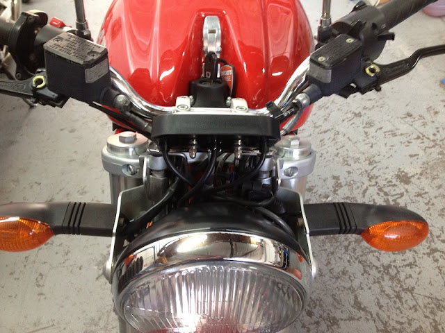
All that was left to do at this point was jam the wiring somewhere that it wasn’t so obvious. The owner elected to do some covering himself, to save paying me to do it, so I positioned all the connectors up in front of the airbox, as below.




So, for a speedo signal I bent up a small sheet metal bracket and mounted the supplied Acewell sensor just in front of the LHF brake caliper. This worked rather nicely. Painted black is was very unobtrusive too, although it makes the photo of it lack detail correspondingly.

The magnet was fitted to the front disc through one of the mounting buttons. I did remove the wheel and re-balance it, as
the added weight was maybe 8 grams.
Acewell offer an engine temperature sensor nominally labelled as “Honda
compatible”. It’s just an M10 threaded
sensor with a graduated output, which conveniently goes into the same hole in the
oil screen plug as the original Ducati sensor.
So out with the old and in with the new.
I think I must have removed the connector (as the next photo shows) so I
could heat shrink the wires. I really
hate uncovered wires. You get good at
disassembling connectors when you do a lot of this.

I made up a little loom to run from the switch connector back to the dash, which went around the back of the clutch cover bulge to hide the big arsed white connector. I guess I could have swapped it for something less obvious (like an AMP Weatherpack 2 pin), but then if a replacement has to be sourced by the owner it wouldn’t be fit and go. I’ve found a very handy automotive loom manufacturer locally (Retro Looms) who stock all the plastic sheathing, which I like using to give the factory look. It just hides add on bits and pieces so much better.
To keep the loom where I wanted it, I bent up a small locating bracket from coat hanger wire mounted to a clutch cover screw. Coat hanger wire is great stuff, and usually zinc plated.

The ECU warning light I ignored. To run this a relay would need to be fitted that would supply power to the dash circuit that is triggered by the original ECU earthing wire earthing the switching side. The owner wasn’t fussed, so the time was saved.
All that was left to do at this point was jam the wiring somewhere that it wasn’t so obvious. The owner elected to do some covering himself, to save paying me to do it, so I positioned all the connectors up in front of the airbox, as below.


And we called it done.


Saturday, June 1, 2013
Bob Brown's 4 valve Pantah heads
.
There's a thread going on the 750F1 and TT forum with some great photos and period article on the 4 valve heads Bob Brown had made for the Pantah motor circa 1985. I've never seen Bob looking so young.
I saw these heads quite a few years ago when Bob had them on display at the FOIM at the Museum.
http://www.ducatittandf1.com/viewtopic.php?f=12&t=10460
.
Monday, March 25, 2013
Adjustable cam pullies for Ducati
.
I received some adjustable cam pullies today from MADASL in the UK. I had sent Mark all the original pullies I could find that came from the days when we fitted the Vee Two adjustable pullies. Mark modifies them to make them adjustable, which suits my love of recycling just fine.
I have 16 in total, 2 round tooth aluminium (originally 916/996SPS), 10 round tooth steel and 4 square tooth steel (pre 98 400, 500, 600, 650 and 750).
The thing I really like about them is that, unlike the Vee Two pullies, you can drill holes through them to fix settings. I did this to a pair of Vee Two ones years ago for the 750 motor in Minnie, but because they have lightening holes in the back section, drilling them usually leads into air. I drilled a lot of holes to get two that were usable. These MADASL pullies have a solid section between the slots on the toothed section and the centre piece is solid. So you can fix a setting, drill a hole, then fix another setting and drill again. Up to 4 times. Woo hoo. Well, if you want to play with timing on the dyno, track or anywhere else anyway.

Prices per pair, including GST and postage Australia wide: round tooth aluminium $200, round tooth steel $170, square tooth steel $170.
.
Wednesday, March 20, 2013
Acewell dash mount plate for Ducati Monster
.
I recently fitted an Acewell ACE-3963 dash to a 2005 M400ie, and as part of the install had some mounting plates cut. I got 10 for my minimum design and set up charge, so have 9 left to try to recoup a little of the money the job cost me. I'll detail the drama later.
They're laser cut from stainless steel plate, with hole spacing to suit both early and late Monsters. The early carb models will need the holes enlarged, currently they're 5mm to suit the ie model mountings. $40 each as is. I really don't want to invest any more time in them, so they're flat and raw. As fitted, the last one was bent and polished.


.
Thursday, February 21, 2013
888SP4 vs 748/853 Dyno chart
.
Today I ran an 888SP4 on the dyno, the first of the old school hotties I've run on the new Dynobike dyno. The runs I had on the old dyno, compared to my 888, showed that the SP motors (pre SP5 anyway) really weren't anything flash power wise. So I compared today's bike with the 853 kitted 748's I've done recently. They've been 748 with 853 kits, modified combustion chambers and std ports. Pretty basic. Blue is 888SP4 with 98/102 cam timing and an eprom sort of to suit ("in progress" runs) and red is 748/853 with 111/108 cam timing and eprom to suit.
 There is the possibility that the 748's more powerful 1.6M ecu (with offset mapping for cylinder 2) allows it a little more power compared to the P7 running the 888 which only has one map for both cylinders. Plus the 748/853 will have more compression. And slightly smaller ports, which seem to work nicely at this capacity.
The 748/853 is certainly a nicer engine to ride, but 36 degrees less cam duration will do that.
.
Today I ran an 888SP4 on the dyno, the first of the old school hotties I've run on the new Dynobike dyno. The runs I had on the old dyno, compared to my 888, showed that the SP motors (pre SP5 anyway) really weren't anything flash power wise. So I compared today's bike with the 853 kitted 748's I've done recently. They've been 748 with 853 kits, modified combustion chambers and std ports. Pretty basic. Blue is 888SP4 with 98/102 cam timing and an eprom sort of to suit ("in progress" runs) and red is 748/853 with 111/108 cam timing and eprom to suit.

The 748/853 is certainly a nicer engine to ride, but 36 degrees less cam duration will do that.
.
Saturday, February 16, 2013
750 Dry clutch photo
.
A photo for a Monster forum question. 750 dry clutch, used on the 750 motor from 1985 750F1 to 1992 750SS and the 1988 851 Tricolore, early 906 Paso and 1990 900SS.

A photo for a Monster forum question. 750 dry clutch, used on the 750 motor from 1985 750F1 to 1992 750SS and the 1988 851 Tricolore, early 906 Paso and 1990 900SS.

.
Friday, February 8, 2013
More on inlet trumpets
.
A bit heavier going (haven't read it myself yet), but some more serious theory on inlet trumpet design
Ok, so now I've read it. It's very interesting, for both its content and, in a somewhat typical way, as to how much change there sometimes isn't when you move from a functional, but simple solution to a more complicated solution. ie, plain pipe to simple radius and then elliptical form. Certainly, the reality of manufacturing an accurate elliptical form as opposed to a rolled edge contrasts strongly against the minimal improvement it offers. And, of course, when you're playing for sheep stations, not having that 1.5% is getting your arse kicked.
Space is also a consideration when you have trumpets close together. ie, Aprilia 990 motors, where oversized inlet trumpets need to be squared where they meet. Although I have been told that fiting large entry, "elliptical style" profile trumpets makes a noticeable difference to engine output.
Looking at the profiles again in figure 5 and remembering what I was pulling apart yesterday, simple radius is 851/888 and aerofoil/elliptical is 916, etc. So I guess Ducati figured there was something in it.
And if you bought trumpets from someone like TPO or WASP or Ducshop you'd find they're large entry, probably elliptical and definitely short and fat.
As a side note, Professor Gordon Blair is a real two stroke expert, and has spent many years at Queens' University in Belfast. He has done lots and lots of very cool stuff over the years.
.
Thursday, February 7, 2013
Varying intake trumpet length and effects thereof.
.
The following page was linked into a thread on the Supersport page of Ducati MS and it's just too good to not try to bring more attention to. Some may see that it's car based and turn off, but that's irrelevant. It's great general info, and the kind that hopefully will convince some reading it to apply and expand on. Or just to think outside the box that most others live in. Hopefully you'll find it as interesting as I did. The part throttle info is particularly useful too.
Many thanks to Dave @ EmeraldM3D for the effort and posting the results.
http://www.emeraldm3d.com/articles/cat/projects/post/emr-adj-length-intake/
.
Tuesday, February 5, 2013
The Island Classic and Ago
.
I went down to the Island Classic for the Saturday to fiddle as required with the MV Agusta Julian McLean had built by Albert Bold, which was doing demo laps ridden by Ago.
Julian is the man from Tahbilk Winery who has been a driving force behind the MV Agusta presence at any motorcycle related function in Victoria for the last 12 or so years. An passionate enthusiast of the type small volume importer's dream about, he also puts his money where his mouth is. Hence the bike built by Albert. It's a Magni frame with a 600 engine taken out to 887cc, dry clutch and chain drive conversions and original MV race team plasma sprayed aluminium front discs. Albert is a very high end machinist, and the titanium throttle linkages, for example, are just a work of art. The bike was featured in the December issue of Motorcycle Trader (Au). 100hp with the megaphones and 155kg. It's a pretty impressive piece of old kit just in itself. Here's a link to Albert's previous MV race bike
Ago turned up in a Fiat 500 with a local lady named Rosa and from the moment he arrived was swamped. He did a couple of sessions both days and the bike went well enough that only a gear lever adjustment was required.
So, to some photos and video.
Julian firing it for the first time on Saturday morning I believe. Rosa in the background and me being the only one smart enough to put their fingers in their ears. Of course, Julian has earplugs. It is godawfully loud. Albert made a 4-1 exhaust for it as well, which made an extra 15hp. Just not old school cool.

I like this photo. Ago in ungracious pose fiddling with boot, me watching on for no apparant reason, photographer extraordinaire Phil Aynsley with the big camera and high vis, Tony Hannagan from Beveltech (Phil's pack horse for the weekend) with little camera and high vis, unknown paramedic. Note to self, pack high vis for next time.

Julian warming it up for Ago, smile hiding the paranoia of hoping like hell nothing goes wrong.

A very short video of Ago down the front straight. First movie with my iPhone, didn't work out quite as planned (kept pressing in the wrong spot). You get the sound though. Strangely, not as loud as it goes past as I expected.
There's a much better (longer) video on the AMCN facebook page, I just can't get it to link.
Sunday, January 13, 2013
A Panigale on the dyno
.
I had a Panigale in on Friday morning to reflash the ecu using the Rexxer tool with a map to suit the QD exhaust system fitted. A race bike from Adelaide on its way to Phillip Island, the reflash was to help fix an overly lean issue when running the QD system with the Termi kit ecu, and included turning most things off - lambda sensors, side stand switch, thermo fans, etc.
On the dyno in Adelaide the QD system had given an extra 20 or so hp through the midrange compared to the Termi kit, so it's a very effective piece of gear. The look may upset some, but that's a personal thing and it has been designed to work first I assume. For those accustomed to recent Termi systems it's shockingly small at 52mm od. Oh the horror. How can it possibly make any power with only a 52mm exhaust.


It went from me down to Dynobike for a run to check the mixture. The curve is smoother than other Panigale dyno runs I have seen, much less top end orientated due to the removal of the midrange hole that seems to have plagued Ducati superbikes since the 999 full systems came along.
Dyno chart
.
Monday, January 7, 2013
Google warning "This site may harm your computer."
.
Best I let my webmaster explain this:
"All my sites were hacked on new years eve. It took two days of running battle to find the cause and permanently remove it.
The hack consisted of inserting links to malware hosted on a Russian website into hidden frames on each web page.
It will take some time for the Google warning to be removed (up to a week).
Sunday, December 16, 2012
Bob Brown's race 851
.
A member of the 851 Yahoo list Posted a link to Bob Brown's 851 race bike that is currently for sale on Bikepoint: 851 Racer. I've seen the bike in person and think it's pretty cool, so I thought I'd put a little bit up on it.
Originally an 851 kit, it had lots of mods over the four or so seasons it was raced (88 - 91). Bob had cylinders made up to allow it to go to nearly 100mm bore for a full 1000cc, and the frame had extra bars welded onto each side of the vertical cylinder that Bob says made a big difference to crankcase life. It cracked a few sets early on, as did all the 851 that were raced. Roche used 36 engines in 1990: Bob witnessed the last one letting go rather impressively coming on to the main straight in the last race of the season at Manfield, after he'd won the title in the first race of the day. From memory the 916 wasn't any better, I'm sure Corser and Fogarty used a similar number of engines in the mid 90's.
Duane Mitchell, who worked with Bob in the era, told me years ago it was very quick, and went past the factory bikes with ease in a straight line. Until it just shut down, which it apparantly did with monotonous regularity. So they pulled the Weber injection and Bob had some manifolds cast to fit a pair of FCR39 to each cylinder and a custom alternator cover to allow a Krober ignition to be fitted to it. Which made it much more reliable.
It's obvious how much time and money went into it, with lots of very cool period race bits like radial master cylinders, etc. And lots of custom/one off work as well. Clearly a money pit, and very cool.
He also has his new in glass case 851 Tricolore Kit listed too: 851 Tricolore Kit
And also this TT2, which was displayed a few (several) years ago at the FOIM at the Museum. It's just gorgeous: TT2
.
Subscribe to:
Posts (Atom)