.
I'll be on reduced hours over the next two weeks due to the school holidays. You can try my mobile or email me and I will be in the factory for some days.
.
Sunday, June 30, 2013
Friday, June 14, 2013
Fitting an Acewell dashboard to a Monster ie with immobilisor
.
There are a few issues that need to be explained with this, as it’s not as easy as first might appear.
1. This is a 2005 M400ie, so it has the immobiliser with red and black keys. The immobiliser unit itself is inside the dash. To enable the bike to run with the original dash removed, the ecu has to have the operating file modified to ignore the immobiliser function. Commonly known as “reflashing”.
2. The indicator control system is inside the dash.
3. The inputs, etc, for controlling the indicators and turning idiot lights on/off tend to be earth based. So to turn a light on, the dash earths the circuit. Or, in the case of the indicators, the LH handlebar switch itself is just an earth path. Whereas on previous models (and as most would expect) it’s a 12V path.
4. The intention was to not cut up the factory wiring, so an original dash could be refitted at some point. This meant finding the corresponding 26 pin connector to suit.
5. The connector to plug into the wiring loom, to make it a nice, professional looking install, is available, but only in PCB form, not wiring loom form. You can get it from RS Online like I did here and the TE Connectivity (who make it) info is here. I also bought some terminals that actually fit the other side (wiring loom) connector, but they too would be good to use to connect the wires to the dash side connector instead of the ferrules (I'm getting ahead of myself, see below).
I went through the wiring diagram and worked out what went where at the dash connector , shown below. Red indicates that I didn't use a given pin or couldn't make it work.

I had some dash mounts cut (water jet from memory) to a design based a
little on a bracket Acewell make, but which is too narrow for the Monster
mounting holes. Then I bent it to mimic
the angle of the Acewell part to make the dash readable when sitting on the
bike and polished it.

I have 9 more, as the minimum set up cost covered 10 in total.
The wiring proved a little more infuriating, and soaked up a quite extraordinary amount of time, as things do when you’re making it up as you go along. And re-doing things that didn’t work as planned the first time round. Etc.
I purchased some little ferrules from Altronic into which I squeezed some solder paste, then slid the ferrule over the connector pin and then slid in the wire to be connected into. With the white plastic end cut off, the slightly flared end of the metal tube is exposed and is very easy to slide the wire into. Then hit it with the soldering iron until the paste went shiny and runny. I found it important to hold the wire in the ferrule, as when the solder went runny it had a tendency to push the wire out a little (or more).
The following series of photos show the product. Unfortunately, the only photo showing the full wiring junction connector is a bit blurry. Which is a bit odd of the iPhone. I must say, the iPhone’s ability to take up close photos of little things is far superior to any camera I’ve ever had.

You can see in this photo the red and black wires that go from the dash connector at the bottom up to the large white connector and then out again to the green or smaller white. These are the common earths and switched power. Likewise, the indicator wires (brown) join at the LH (small white) or RH (green) connectors.
At the connector, I slipped heat shrink over the wires before fitting them so I could then insulate them individually.

 A salesman at one of the electronics shops had recommended using a two
part epoxy to ‘pot’ the back of the connector once finished, but I asked Jack
at City Auto Electrics about this and he said he’d just heat shrink it. That way, it’s not permanently fixed.
A salesman at one of the electronics shops had recommended using a two
part epoxy to ‘pot’ the back of the connector once finished, but I asked Jack
at City Auto Electrics about this and he said he’d just heat shrink it. That way, it’s not permanently fixed.


Power for the m-Flash was taken from the loom side of the ignition switch connector, from one of the wires that receives power with ignition on. I simply removed the original terminal form the connector, cut off the terminal and replaced it with a new one with the m-Flash input wire added. It’s just a typical spade terminal with locking tab. In the photo below, in the centre location, yellow wire is original, larger red m-Flash input.

From the connector the power wire runs through a 10A inline fuse holder and into the m-Flash. The output wire of the m-Flash I fitted into the loom connector for the LH switch block in place of the wire that originally provided the earth path for the central terminal of the switch, used to earth the flasher circuit activation wire inside the original dash. This way, power will flow through the switch and into the new dashboard wiring, where it will be sent out 3 ways: idiot, front and rear.
The wire that needs to be removed from the loom connector to the LH switch block (as per the photo below) is the (edit, was previously wrong) second from the bottom wire on the RH side, which is black. As a reference, the top LH hole doesn't have a wire in it. In its place (using an AMP weatherpack terminal) goes the m-Flash output wire.

I just heat-shrinked the original wire and zip-tied it out of the way (or maybe poked it up the plastic sheath). Not important, it’s an earth anyway.
So now we have power from a switched source through an indicator control unit into the LH switch block and out again into the wiring loom going to the dash. As the wires to each indicator also go through the dash connector, joining the input wire to the two respective indicators (front and rear for each side) completes the power circuit.
Oil pressure was easy, as the Acewell uses the normal downstream earth switch to complete the circuit and turn the light on.
Similarly the Neutral light. As this is a single wire neutral switch model, it again uses a downstream earth switch to complete the circuit and turn the light on. On an earlier model with a two wire neutral switch you could earth one side of the switch and connect the other side to the dash to make it work.
Luckily, the tacho worked from the ECU output. The tacho input in the Acewell was set to 0.5 (signals per revolution I think, meaning 1 signal per cycle).
Unfortunately, that was the end of my luck. The original speed signal, engine temperature and fuel gauge circuits wouldn’t play. I’m not sure if the fuel gauge reading was some error on my part, as I don’t understand why it wouldn’t work or if I managed to kill the sensor (not sure how), but I couldn’t make it work.
I recently fitted an Acewell 3963 dashboard to an M400ie, in place of
the original that had gone rather wacky.
The owner wanted to move away from the original dash, and I had a 3963
in stock that I was planning to fit to my Monster at some point. So I figured, “how hard could it be?” Or, as it turned out, "how much money can I
throw away?" A lot, as it turned out.
There are a few issues that need to be explained with this, as it’s not as easy as first might appear.
1. This is a 2005 M400ie, so it has the immobiliser with red and black keys. The immobiliser unit itself is inside the dash. To enable the bike to run with the original dash removed, the ecu has to have the operating file modified to ignore the immobiliser function. Commonly known as “reflashing”.
2. The indicator control system is inside the dash.
3. The inputs, etc, for controlling the indicators and turning idiot lights on/off tend to be earth based. So to turn a light on, the dash earths the circuit. Or, in the case of the indicators, the LH handlebar switch itself is just an earth path. Whereas on previous models (and as most would expect) it’s a 12V path.
4. The intention was to not cut up the factory wiring, so an original dash could be refitted at some point. This meant finding the corresponding 26 pin connector to suit.
5. The connector to plug into the wiring loom, to make it a nice, professional looking install, is available, but only in PCB form, not wiring loom form. You can get it from RS Online like I did here and the TE Connectivity (who make it) info is here. I also bought some terminals that actually fit the other side (wiring loom) connector, but they too would be good to use to connect the wires to the dash side connector instead of the ferrules (I'm getting ahead of myself, see below).
I went through the wiring diagram and worked out what went where at the dash connector , shown below. Red indicates that I didn't use a given pin or couldn't make it work.


I have 9 more, as the minimum set up cost covered 10 in total.
The wiring proved a little more infuriating, and soaked up a quite extraordinary amount of time, as things do when you’re making it up as you go along. And re-doing things that didn’t work as planned the first time round. Etc.
I purchased some little ferrules from Altronic into which I squeezed some solder paste, then slid the ferrule over the connector pin and then slid in the wire to be connected into. With the white plastic end cut off, the slightly flared end of the metal tube is exposed and is very easy to slide the wire into. Then hit it with the soldering iron until the paste went shiny and runny. I found it important to hold the wire in the ferrule, as when the solder went runny it had a tendency to push the wire out a little (or more).
The following series of photos show the product. Unfortunately, the only photo showing the full wiring junction connector is a bit blurry. Which is a bit odd of the iPhone. I must say, the iPhone’s ability to take up close photos of little things is far superior to any camera I’ve ever had.

You can see in this photo the red and black wires that go from the dash connector at the bottom up to the large white connector and then out again to the green or smaller white. These are the common earths and switched power. Likewise, the indicator wires (brown) join at the LH (small white) or RH (green) connectors.
At the connector, I slipped heat shrink over the wires before fitting them so I could then insulate them individually.


To make the indicators work I had to convert the indicator switch to a
power in/out style. To do this required
a few things.
First, I used a motogadget m-Flash
solid state flasher control unit. This little
(and I mean little) unit will supply an on/off/on/off/etc voltage output
whenever a load is placed on it. There
are a few other versions of it available I believe, but this was the most
obvious one I found.
Power for the m-Flash was taken from the loom side of the ignition switch connector, from one of the wires that receives power with ignition on. I simply removed the original terminal form the connector, cut off the terminal and replaced it with a new one with the m-Flash input wire added. It’s just a typical spade terminal with locking tab. In the photo below, in the centre location, yellow wire is original, larger red m-Flash input.

From the connector the power wire runs through a 10A inline fuse holder and into the m-Flash. The output wire of the m-Flash I fitted into the loom connector for the LH switch block in place of the wire that originally provided the earth path for the central terminal of the switch, used to earth the flasher circuit activation wire inside the original dash. This way, power will flow through the switch and into the new dashboard wiring, where it will be sent out 3 ways: idiot, front and rear.
The wire that needs to be removed from the loom connector to the LH switch block (as per the photo below) is the (edit, was previously wrong) second from the bottom wire on the RH side, which is black. As a reference, the top LH hole doesn't have a wire in it. In its place (using an AMP weatherpack terminal) goes the m-Flash output wire.

I just heat-shrinked the original wire and zip-tied it out of the way (or maybe poked it up the plastic sheath). Not important, it’s an earth anyway.
So now we have power from a switched source through an indicator control unit into the LH switch block and out again into the wiring loom going to the dash. As the wires to each indicator also go through the dash connector, joining the input wire to the two respective indicators (front and rear for each side) completes the power circuit.
Oil pressure was easy, as the Acewell uses the normal downstream earth switch to complete the circuit and turn the light on.
Similarly the Neutral light. As this is a single wire neutral switch model, it again uses a downstream earth switch to complete the circuit and turn the light on. On an earlier model with a two wire neutral switch you could earth one side of the switch and connect the other side to the dash to make it work.
Luckily, the tacho worked from the ECU output. The tacho input in the Acewell was set to 0.5 (signals per revolution I think, meaning 1 signal per cycle).
Unfortunately, that was the end of my luck. The original speed signal, engine temperature and fuel gauge circuits wouldn’t play. I’m not sure if the fuel gauge reading was some error on my part, as I don’t understand why it wouldn’t work or if I managed to kill the sensor (not sure how), but I couldn’t make it work.
Edit - I fitted an Acewell to one of my Monsters recently and found the input to the dash for the low fuel light was an earth input, not 12V as I had assumed. In that instance, I fitted a relay that was switched on by the 12V output of the low fuel sensor, and the relay main circuit (30/87) was an earth circuit that gave a switched earth into the dash input. I would expect this dash was probably the same, and I just didn't notice the detail in the instructions. So be aware of input type.
So, for a speedo signal I bent up a small sheet metal bracket and mounted the supplied Acewell sensor just in front of the LHF brake caliper. This worked rather nicely. Painted black is was very unobtrusive too, although it makes the photo of it lack detail correspondingly.


I made up a little loom to run from the switch connector back to the dash, which went around the back of the clutch cover bulge to hide the big arsed white connector. I guess I could have swapped it for something less obvious (like an AMP Weatherpack 2 pin), but then if a replacement has to be sourced by the owner it wouldn’t be fit and go. I’ve found a very handy automotive loom manufacturer locally (Retro Looms) who stock all the plastic sheathing, which I like using to give the factory look. It just hides add on bits and pieces so much better.
To keep the loom where I wanted it, I bent up a small locating bracket from coat hanger wire mounted to a clutch cover screw. Coat hanger wire is great stuff, and usually zinc plated.

The ECU warning light I ignored. To run this a relay would need to be fitted that would supply power to the dash circuit that is triggered by the original ECU earthing wire earthing the switching side. The owner wasn’t fussed, so the time was saved.
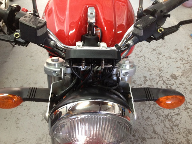
All that was left to do at this point was jam the wiring somewhere that it wasn’t so obvious. The owner elected to do some covering himself, to save paying me to do it, so I positioned all the connectors up in front of the airbox, as below.


So, for a speedo signal I bent up a small sheet metal bracket and mounted the supplied Acewell sensor just in front of the LHF brake caliper. This worked rather nicely. Painted black is was very unobtrusive too, although it makes the photo of it lack detail correspondingly.

The magnet was fitted to the front disc through one of the mounting buttons. I did remove the wheel and re-balance it, as
the added weight was maybe 8 grams.
Acewell offer an engine temperature sensor nominally labelled as “Honda
compatible”. It’s just an M10 threaded
sensor with a graduated output, which conveniently goes into the same hole in the
oil screen plug as the original Ducati sensor.
So out with the old and in with the new.
I think I must have removed the connector (as the next photo shows) so I
could heat shrink the wires. I really
hate uncovered wires. You get good at
disassembling connectors when you do a lot of this.

I made up a little loom to run from the switch connector back to the dash, which went around the back of the clutch cover bulge to hide the big arsed white connector. I guess I could have swapped it for something less obvious (like an AMP Weatherpack 2 pin), but then if a replacement has to be sourced by the owner it wouldn’t be fit and go. I’ve found a very handy automotive loom manufacturer locally (Retro Looms) who stock all the plastic sheathing, which I like using to give the factory look. It just hides add on bits and pieces so much better.
To keep the loom where I wanted it, I bent up a small locating bracket from coat hanger wire mounted to a clutch cover screw. Coat hanger wire is great stuff, and usually zinc plated.

The ECU warning light I ignored. To run this a relay would need to be fitted that would supply power to the dash circuit that is triggered by the original ECU earthing wire earthing the switching side. The owner wasn’t fussed, so the time was saved.
All that was left to do at this point was jam the wiring somewhere that it wasn’t so obvious. The owner elected to do some covering himself, to save paying me to do it, so I positioned all the connectors up in front of the airbox, as below.


And we called it done.


Saturday, June 1, 2013
Bob Brown's 4 valve Pantah heads
.
There's a thread going on the 750F1 and TT forum with some great photos and period article on the 4 valve heads Bob Brown had made for the Pantah motor circa 1985. I've never seen Bob looking so young.
I saw these heads quite a few years ago when Bob had them on display at the FOIM at the Museum.
http://www.ducatittandf1.com/viewtopic.php?f=12&t=10460
.
Subscribe to:
Posts (Atom)