Saturday, December 23, 2017

Ducati 43mm non adjustable forks 1999 - 2005 ish - The ones with an awful lot of low speed damping.


There's some 43mm non adjustable forks fitted to the smaller engined Monster and SSie from 1999 to 2005 or so, made by Showa and Marzocchi and someone else who possibly makes them under license from Marzocchi (maybe?) that have quite amazing amounts of low speed damping.

The easiest way to recognise them is to strip them and try to get the oil out of the cartridge.  It would appear that the only way for the oil to get out is between the rod and corresponding opening in the top of the cartridge.  A few drops at a time.  I really don't understand that.

As an aside here, after this style fork they went to an externally visually similar (I'd say probably identical) fork which has rebound damping only on one side and compression (allegedly) on the other.  These are the forks in the S2R800, 695 and late 620 and 400 models.

I don't see many of these bikes for fork oil change services, but I did an oil change on a 1999 750SSie a couple of years ago and tried going down to 5 weight oil to reduce the damping.  It didn't really seem to make much difference, and that's as far as I got with that bike.

The oil spec for those forks is Showa SS-8, which I found a spec for on the transmoto.com.au/comparative-oil-weights-table of 36.8 cST @ 40 degrees C.  That's a tiny bit lighter than Maxima 10 weight (32 cST on the linked table, but 37.4 cST in the Maxima blurb), but generally typical for the available range of 10 weight oils.  The Maxima 5 weight is 16.2 cST, which is a big difference that gave little change.

The later non Showa ones are listed as using Shell Advance Fork 7.5 in the 2001 M400/600/750 manual, whose viscosity is 22 cST in the Shell specs.

Many years ago there was a posting on the Ducati Monster Forum from a fellow from NSW who had Shaun at D Moto have a play with his M800ie forks, which would have been of this style.  I rang Shaun to ask him what he had done and he said he'd drilled some holes in the cartridge above and below the piston travel to reduce the low speed damping.

So, recently, when I had a 2003 M400ie come in for some fork seals, I took the oppurtunity to have another go at making them work.

The photo below shows the marking on the inside of the lower leg.  Not sure which company this is.  The cap has a 19mm hex.


removed the cartridges (undo bottom screw) and tried to get the oil out of them, the total unsuccessfullness of which confirmed I had the forks I thought I would.  This is what the cartridge looks like (RH end is the bottom)


The hole you can see at the RH end is where the oil enters the cartridge to fill it on the unlikely occasion it is empty.  This is a non serviceable cartridge, unless you cut it open and then weld it up again.

I made a guess on where I thought the compression valve at the bottom would end and where the piston would be moving, and drilled a couple of holes to allow the oil to bypass the shim stacks.  This is exactly what most adjusters do on adjustable forks - open a hole and allow oil to bypass the technologically superior shim stack via a very technically inferior hole.

Oil flowing through holes is how damping rod forks (old style) work, and that's why they have no low speed damping and often lots of high speed (depending on the diameter of the hole and what weight oil you run).  At some point the hole, which provides no resistance to the oil as it flows through it at low speed, effectively becomes solid as oil is forced through it at increasingly higher speed.  The bigger the hole, the higher the speed at which it becomes a restriction.

The shim stack is very variable and adjustable (if you can get to it) and a much better idea to modify.  If it is any good anyway - if not, you often end up bypassing it with an old school hole.

The holes I drilled were 55mm and 230mm up from the very bottom of the cartridge, as below.


The bottom hole could have been 50mm up I'd think - with the drill bit through the hole you could just feel the end of the piston hitting the bit with the rod fully compressed.  It wasn't blocking the hole though.

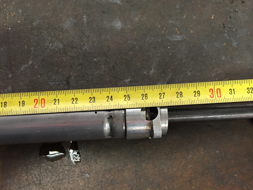
The holes shown are the initial 1mm holes.  I used some ti-nitride drill bits and my air drill, which was the only one I had with a chuck small enough to hold the little drills. They drilled through nicely without pressure on the bit pretty much.  The last time I tried drilling holes in some cartridges I broke a couple of drills and it all got a bit messy.  This time no worries at all.

A point to make at this time - after drilling the holes, it's a very wise idea to not move the rod at all if possible.  That oil inside the cartridge, previously impossible to remove, is now very keen to spray out all over you or whatever else the hole is pointed at.  Old fork oil is not a nice liquid to coat one's self with.  You'd almost go as far to say that wearing a hundred ml or so of fork oil is justification enough to throw clothing in the bin.


Once the 1mm holes were drilled I refitted the cartridge, filled the leg with Maxima 7 weight oil (26.7 cST), bled it up and had a assessment of the result.  The low speed rebound was much reduced, and felt somewhat normal-ish. The reduction in low speed compression wasn't anywhere near what I was hoping for, so I went to 1.5mm and then 2mm to reduce it further.  With the 2mm hole the compression felt on what I would call the high-ish side of normal, but much, much less than originally.  Normal is also a relative term - often the Ducati forks seem to have almost no compression damping at all.  The later comp only fork leg has a hole larger than 2mm about 100mm up the cartridge from memory, and no compression damping until the piston has moved down past the hole (the last third or so of travel).  

A couple of points:

1/ The manual calls for 7.5 weight oil, which will have been chosen for some reason.  I used Maxima 7 weight because I wasn't sure what the impact would otherwise be on the high speed damping.  All the hole drilling is concerned with is the low speed.  The high speed will be set by the oil weight.

2/ I'm no suspension expert, nor do I have the skill required to make an assessment of high speed damping and requirements thereof.  So the decision regarding oil weight was more to reduce the number of changes being made, and assuming there was validity in the 7.5 weight spec.  It may turn out that there is too much or too little high speed damping and that a different oil weight would be more desirable.  Or it may have a mismatch and ideally require different weights for each direction, which is impossible to achieve.

3/ This bike is an M400ie commuter, so it's a pretty soft target in terms of making a big improvement without causing problems.  The crappier things are to start with, the harder it is to make them worse.  Well, usually.

In terms of the hole size chosen, it was a guess (I actually think it was the conversation with Shaun, and someone else from somewhere) and trial and error.  You could also vary the number of holes.  A 2mm hole is 4 times the area of a 1mm hole, so you could also try 2 of 1.5mm or 4 of 1mm holes which would effect the low speed similarly, but reduce the impact on the mid and high speed damping.  The 1mm hole will effectively go solid much earlier than a 2mm hole.  As well as being 1/4 the size, the circumference, and hence boundary layer effect on flow, is proportionally higher.  Four of the 1mm holes should work much the same at very low speed, but will give more mid speed damping than 2 of 1.5mm holes, which in turn would give more mid speed damping than a single 2mm hole.

Someone who specialises in suspension mods would have a much better idea of hole sizing.

At this point I had a 1mm bleed hole for the rebound damping and a 2mm bleed hole for the compression damping with 7 weight Maxima Racing Fork Fluid set to 135mm.  The oil height specified in the manual is 80mm, which I know from my previous oil height experiments gives a very aggressive air spring effect.  As I was also going to make a spring rate change, I likewise made an oil level change.

The owner of the bike weighed around 75kg, so I didn't want to go too hard with the springs.  If it was mine, I'd be going at least 0.90kg/mm.  I tend to cut down the original springs if I can, and use a spring rate formula to work out how much I need to cut.

The spring rate calc is (G x d x d x d x d) / (8 x N x D x D x D)

where G is Young's Modulus (material property, 76.9GPa)
          d is the wire diameter
          N is the number of working coils
          D is the spring mean diameter

The original spring is 292mm long, 4.8mm wire diameter, 38.6mm outside diameter and has 22 working coils.  It is a typical Ducati dual rate spring, where it has a tighter wound section with constant coil spacing over each section.  See the top spring in the photo below.  The spring rate given by the formula is 0.606kg/mm for the total spring in its initial travel.  Too soft.


Often, with the Ducati springs, the secondary rate is about what you want, so you cut off the tight wound coils, square and grind the end and away you go.  But, in this case, there are 22 total working coils with 14 open and 8 tight.  The open coils are 10.3mm apart, the tight coils 4.4mm apart.  This means that when the spring has been compressed 22 x 4.4 = 96.8mm, the tight section will be fully compressed and the open section will become the working section.

Unfortunately, by the above formula, the open section being 14 working coils gives 0.953kg/mm.  For a rider weight of 75kg on a Monster that's too much.  Appropriate for an ST, but not an M.  Also, if we have 14 working coils with 10.3mm between each coil the available spring compression is around 144mm.  These forks have around 120mm of travel and you usually have 15mm or so of preload, requiring at least 135mm of compression.  I'd not like to run a spring to within 10mm of coil bind.  So, for this spring, cutting is not an option.  You could cut off less coils, but it would still be a dual rate spring that became a single rate spring of 0.95kg/mm much sooner.

The spring rate I wanted was in the 0.80 - 0.85kg/mm range.  As it happens, the oem rate of an ST series spring is 0.83kg/mm.  I tend to have a few old ST series springs kicking around as I replace quite a few of them with 0.95kg/mm springs, so I grabbed a pair from the old spring stock and checked them against the originals.  As you can see in the above photo, the linear rate ST series spring is 2mm longer than the original Monster spring and preload spacer.

There were a couple of issues I had to attend to to make them fit.  I had to machine about 0.4mm off the spring inner guide (a ribbed plastic sleeve that goes over the cartridge piston rod and inside the spring) to allow the ST spring to slide over it.  Had I used some of the aftermarket springs available I may not have had to do this, but using s/h springs from the pile I have to hand not only recycles a processed piece of natural resource and shares the love, it also knocks about $200 off the job so we can afford a little lathe work.

The ST springs were about 2mm longer than the original springs and preload spacers. The original set up had given 16mm of spring preload as assembled, which I wanted to replicate.  But one issue was that the stamped C plate (see photo below) that holds the spring in didn't sit evenly on top of the ST series spring due to the spring inside diameter.  Well, it didn't sit nicely on top of the original spring either, and the forks had been incorrectly assembled previously 
with the preload tube under the spring as it came apart.  Ideally I needed a piece of the original preload tube to sit on top of the spring under the C plate, so cut a couple of 6mm slices off one of the original preload tubes.  To allow for the increased length (now 8mm over original), I shortened the square aluminium nut that locked the top cap onto the rod by 8mm so that the stamped C plate would sit 8mm higher.  Simple.  Again, see the photo below for the 3 mentioned pieces: nut, spacer, stamped C clip.  Should have put the spacer below the C clip, that'd make more sense.


Back together again, with the bottom on the floor I could almost fully compress the legs with a big bounce of my weight, which seems to be a pretty good test of oil height impact, etc on any fork I find.  It's amazing how much you can feel the impact of 30mm of oil height in a simple test like this.

The top of the cartridge has a recess that a bush on the rod goes into, which when the recess is full of oil becomes a hydraulic bump stop of sorts at full compression.  I though that was kind of cute, although it did spray me with oil a couple of times.


So that's where I ended up.  On the road on my usual road test loop, which is fairly undemanding in a dynamic sense, it felt quite nice.  Before I'd started playing with it (leaking fork seals were the stimulus), the front end didn't really move much. Not too stiff, just reluctant.  Now feels like a normal front end. The owner is very happy with it.  Even though the spring rate is 33% higher, the fact the forks previously didn't move very much due to the excessive damping has lead to them feeling softer and simply more compliant with the road.

It'd be nice to have someone who knows suspension give feedback on the result, as it could undoubtedly be improved upon further.  But, as a simple starting point, and one that's easily repeatable in the back yard, it's pretty good.

Saturday, November 18, 2017

Sunday, November 12, 2017

My revised muffler baffle for Minnie

This is the baffle I knocked up prior to riding to the FOIM.  I realised I was later than I expected at that point, so it was quick.  Not pretty, but very effective as it happens.  Many years ago Mark Harris who was Madaz at that time told me a baffle needs to fully obstruct the linear flow of the gas to really work, but without that obstruction being overly restrictive as such.  The previous one was a shorter tube much the same size with an open end, like a Staintune baffle would be.  It really didn't make that much difference.

Not sure how this will work on the dyno.  Not sure that I want or care to find out.


An end for Minnie's makeover

At the start of the week I had a "to do" list for Minnie to get her ready for the Festival Of Italian Motorcycles today.


"Front brake work?" at the top literally meant "does the front brake work?  With the second front disc adding a corresponding caliper, the demand for front brake fluid displacement increased by 100%.  The original single disc front master cylinder is 13mm, the original dual disc front master is either 15 or 16mm, depending on model.  My 851 had a 15mm master originally, which I replaced with a 16mm (from my Sport 1100i after I crashed it I think).  I was curious to know how it would work with the 13mm, as I'd never tried it before.  My feeling was it would just have a lot of travel and probably some good feel.  But the reality was you could pull the lever back into the bars with little discernable increase in pressure.  Like it had air in it - I spent ages bleeding it thinking I'd screwed that up somehow.  Whereas on the road it gave a lot of travel before it finally started to stop, without a lot of feel as to when it was going to stop.  So, curiosity answered, larger front master needed.  That was Monday's decision.

The 15mm master is 31% bigger, the 16mm 50% bigger.  I went looking for my 15, but couldn't find it.  I figured the best way to find it was to buy and fit a new 16mm master (it worked).  Because the look for this bike is the "coffin" style  masters, I had to buy a new one as the Sport 1100i 16mm now on the 851 is a remote reservoir style.  The new one turned out to be the new style with the larger fluid reservoir, meaning the lovely Chinese billet reservoir caps I'd bought the week before didn't fit anymore.  Great.  And the pivot pin, which is cad pacified (gold zinc) plated on the originals, is now silver and I've spent a heap getting all the fasteners replated so I had to refit the "not so shiny like the rest of the fasteners" original.  Hmmmmmm.  Did have a nice new lever though.

But, it worked.  Funny how a 100% increase in fluid demand is happily dealt with by a 50% increase in delivery.  The very cool floating cast iron discs don't like sintered pads, so I went through my stash of old single pin original pads and found a couple of pairs that were bead blasted and fitted.  Stops better than it used to with the single disc, but with the organic style pads you just don't get that initial bite that I do enjoy so much.  Maybe some new Ferodo Platinums will help.  More money.

So that was #1 ticked off the list.

The speed sensor for the Acewell was the next issue.   With the caliper adapters there wasn't anywhere to fit a little bracket like I had previously.  I liked the little bracket, as it is a serviceable solution (as in you can remove and refit).  My mounting as below is not - double sided taping it to the bottom of the fork leg.  The sort of thing that customers do that annoys me.  I drilled and tapped a thread into the disc carrier and fitted the little magnet and away we went.  Easy.  Compared to the 120/70-17 circumference of 1860mm, the 130/60-16 measured at 1735mm.  But after riding it around with the iPhone zip tied to the handlebar clamp and the speedo app running, I increased the setting to 1760mm (1.5%) to bring the speedo in on the underside of accurate.  #2.


The tacho drive is due to this being an SS engine, which has a cable drive tacho.  I do have a Monster blanking plug somewhere (at least one in an engine), but laziness had kept me from moving it any closer to this engine.  I found a little blue rubber cap that fitted just fine, and it has resisted bailing for quite some time now.  But, I figured I'd make it a little nicer and I like machining stuff, so turned up a little cap and screwed it on with an old cable collar (I always cut them off old cables just in case).

The rocker covers were looking a bit crappy, but I didn't have any paint close to hand that I thought might be a good fit.  Well, I have some gold that is possibly a good match for the Paso rockers covers that I always liked, but didn't think it'd match the rest of the bike.  I didn't want anything bright, but didn't have any shades of real grey so I gave them a coat of cold gal.  With the rocker covers bead blasted and heated with the heat gun the cold gal dried at it hit them, the finish is rather matt and coarse and lighter than I expected, but it's there and that gets it ticked off the list.


This engine has the D on the timing belt covers and the DUCATI on the alternator and clutch covers, so I scraped, rubbed and polished the paint off.  I thought it was a nice little detail.


I needed a new clutch lever and reservoir cap (to match the new original on the brake master) and the master body had a fair bit of scraping along the road damage near the pivot.  I figured the best solution was a complete new master.  Easy.

I was looking for something to fashion a brake line bracket from to hold the front brake hose at the lower triple.  I usually find old horn mounts are good for this sort of stuff, and I stumbled across a nice gold zinc one.  Just lovely.  A quick bend and on.  Another one down.


The last point on the list - frame bolt caps - had me loking for the rubber caps that go into the tubes for the engine/frame bolts, and it took me to a tub that I thought (possibly correctly) contained mostly parts of the disassembled 400SS.  And in that tub, I found the 15mm front brake master cylinder.  Bugger.

At least I know where it is, so now I can lose it again for the next time I want to use it.

To make the inside of the muffler end cap a little less obvious I tried to clean up the inside with some scotchbrite (which didn't work as hoped polish wise), then ran some masking tape around the inside of the outer and the machined end cap.  I had machined the end cap prior to giving it to Ken when he made the muffler so I could fit a baffle as used in the last muffler.  It didn't make a lot of difference sound wise, so I made another with a smaller and longer internal tube and then folded a piece of sheet metal into a u shape and welded it on.  Suitably low rent, and effective I must say.  I don't really know if it's that loud, but the high outlet certainly gets into my helmet.


And today at the FOIM, after a lot of them had left.  I think it might be finished at this point.  

Now I can pull it apart again.


Tuesday, November 7, 2017

Ducati 2V cam profile comparisons


I made up a fairly basic jig to hold a 2V head and a couple of dial gauges so I could plot out some 2V cam profiles.  I used a spare 400 head I have which is a 3 bearing style head, as opposed to the later 620/695/800 2 bearing head.  

For test samples I had the following, with their Ducati specs and the measured specs for comparison.  Click on any image or graph to make it bigger as required.  The dyno graphs are generally from various reports if you want to look for more info there.


I borrowed some P (Montjuich, Laguna Seca, Santamonica) and 8J (900ie) from Chris Boucher and Peter Nuss on the TT1/F1 forum, so a big thank you to them.  The 2S 620 cams had been modified to go into the 3 bearing head as used in the previous installment of the Minnie the 400 debacle.  I didn't have any 800 cams (3X and 3U?), and they wouldn't fit into these heads anyway.

The rig was very much analogue.  I did look at some digital dial gauges with outputs, but the cost put me off that pretty quickly.  I did the testing at nights, which involved me sitting down, reading the degree wheel and dial gauges every two degrees of cam rotation and typing that into my spreadsheet. It started out as fun, but after the first couple it got a bit dreary, and by the last two was just downright tedious.  I was very glad to see the end of the job.


Because I was reading the degree wheel every two degrees, I have cam lift values corresponding to every four degrees of crank rotation.  I wasn't going to take readings every degree of the degree wheel - I would have lost my mind.

The result is the following.


Separating the Pantah head cams out (vertical cylinder carb at rear of head), the following has the Pantah (labelled PH in the chart), F1 and P cams.  The F1 cam is the same profile at the R, but ground 8 or so degrees advanced.  I had a set at one time that had OE and MV stamped on them.  To accommodate the higher inlet valve lift at overlap (inlet valve opening) that advance brings, the F1 pistons have comparatively deeper valve reliefs than the later 750 pistons.  From memory they have higher crowns too for more compression.  Although both would be less than that required for the P cams fitted to the Montjuich, Laguna Seca and Santamonica models.


Immediately obvious is the extra duration and valve lift of the P cam.  It's what I would call old school, and what would have been referred to back in the day as "race", or even "full race" if you were going for effect.  Cue the oohs and aahs and air sucked through teeth.  As with most of the old school race stuff, it's kind of crappy now that good ports and cams are well understood.  The greatly increased valve lift at overlap (exhaust closing, inlet opening) is what requires far deeper valve reliefs.

I don't understand what it is about the F1 cam that made them want to use that over the original Pantah cam.  Similar 1mm lift duration and less lift doesn't really seem like an advancement to me.  Bruce Meyers told me the Pantah cams were better in his experience, and now I can see visually that I would expect that to be the case.

Next the "Paso" style engines, which simply means vertical head rotated with inlet at the front.  Although I think it was the prototype Elefant that first displayed the reversed head in 1983.  Anyway, they started out with the R cam, then with the 906 came the HT cam, the HZ in the ST2 in 1997 and the 8J in the 900SSie in 1998.  Also available for them were the Vee Two cams, the 210 grind being the same as the DP 06090 and Gia.Co.Moto GM09 and the 212 grind.

The 2S grind, which was fitted to the new 620 engine of 2002, was the first of the two bearing cam fitments.  This cam was only fitted to the 620.  The 800 also used the two bearing cam with similar duration to the R cam, but with 1.5 - 1.8mm more lift.  This was marked 3X (also 3U?).  It specs like quite a good cam and worked well in the 800, which made 900 ish hp with the 900 size valves, but 15 or so degrees less duration.  This cam was then used in the M695 and M400ie.

First up, R vs 2S.


Dyno comparison from Minnie the 400.  Red is R @ 108 inlet centreline, blue 2S @ 112 inlet centreline and green 2S @ 107 inlet centreline.


R versus HT.  The R cam was also used in the W head M900 engines and the Cagiva Elefants and Gran Canyons.


Dyno comaprison from my M750 with ported, big valve heads.  R @ 114 is blue, HT @ 107 is red.  I later realised that I had taken some ignition advance out of it which did hurt the power at the top end.  But I assume both curves would have been similarly affected.  It was nowhere near as much change as I expected (or had hoped).


This is a 750SSie I did prior to my M750.  Green is R as delivered, blue is HT @ 119 and red is HT @ 107.  I did quite a bit of tuning to it with the HT cams @ 119, both fuel and ignition advance.  The 107 run is with the same mapping, just a cam timing change after the engine came apart and the piston inlet valve reliefs were machined 1.5mm deeper to allow more cam advance.


Removing the HT @ 119 run makes it a bit clearer.


R vs 8J


Dyno comparison from a Cagiva Gran Canyon, which is a 900ie engine with the W heads - R cams and 41/35mm valves.  We fitted 8J cams to it set to 106 degrees inlet centreline in the hope it would make some more power.  Not enough, as it turned out.  It was still 8 or so down on the 900SSie engine with 43/38mm valve V heads.

The 900 cams - HT, HZ (ST2) and 8J.  The ST2 cam has gained a reputation for being the best, and of working well in a 900 carb engine, but I've never seen any dyno proof of that.


There's really not a great deal of difference between the 8J and HZ.  The 8J inlet peaks a little earlier and longer.  If you compare the area under the curves, again there's little difference.  

If we add the two Vee Two cams to the above, you get a somewhat confusing graph, but the two Vee Two cams stand out for their similar exhaust profiles to the HZ and 8J and their similar inlet profiles to each other.  The 210 definitely works at a lower rpm range than the 212.  Both of these cams don't match their specs, as below:


HT vs 210.  The inlet duration is not much different, and the 210 certainly has a lot more area under both curves.  But the lesser exhaust duration is what hurts it at the top end.


Dyno comparison of a 900SS, fitted with Omrae slip on mufflers and otherwise std.  Well, I believe the after run is the first of the tuning runs.  Red is HT as delivered, probably in the 113 - 115 degrees inlet centreline range, blue 210 @ 105 I think.  It certainly picked up the midrange, which is what the long manifold carb motors are all about.


That's it for direct comparisons.  I'll finish by quoting Bruce Meyers, who has a lot of experience playing with these engines.  He posted this in relation to hotting up the 800 engines on a forum some years ago, and I think it's a good piece for reference:

--900SS Carby cams: give a nice increase from 4000 rpm up with avg +4 rwhp over stock cam.

--ST2 cams: Net a bit more on top end rwhp with no loss of midrange.

--900SSie cams: Net alot more on top, maybe 2-4 more rwhp than carby cams but a slight loss 
at 4500 rpm. I think that dip could be tuned out with a good pipe.

--V2 212 cams: Exactly the same as 900SSie cam results

--V2 210 cams: Exactly the same as ST2 cam results

Tuesday, October 10, 2017

Minnie the 400 Monster gets 620 cams: One has one's arse handed to oneself yet again.

.
Some time ago I bought some 620 cams and sent them out to Ian Drysdale to have them modified to suit the earlier 3 bearing heads so I could try them in other things - namely my 400.  I've also made a rig to hold a spare 400 head I have that allows me to read cam lift as the cam is rotated.  It's all very analogue (ie, me sitting there looking at a degree wheel and dial gauges) and gives me valve lift every 4 degrees of crank rotation.  You'll see more of that in the future.  This way I could compare the 400/600/750 cam (labelled R) and the 620 cam (2S), as below.


Spec wise, the 2S is like the R, but with the inlet closing 15 or so degrees earlier and with more lift on both inlet and exhaust.  In profile, the exhaust is a bit bigger and has an earlier peak while the inlet is as expected.  The reason I wanted to try the 620 cam is that the 400 has a long flat power curve at the top end - it's pretty flat from 9 to 11.  As such, I was wondering if it was over cammed, and figured the 620 cam should be better and a good illustrator of why.  What I was hoping to see on the dyno with the 620 cam was peak power of the same or more, the peak moved down the rpm range and the power dropping away after the peak.

Spec comparison as below:


I fitted the 620 cams at the inlet centreline spec of 112 degrees, and with the drilled pullies I could advance them to 107 to see what happened.  I was also considering retarding them on the dyno as well, but didn't bother in the end.  As usual, the results sucked all the motivation right out of me.

Red is R cam at 108 degrees, blue is 2S cam at 112 degrees and green is 2S cam at 107 degrees.  The midrange improvement is between 5,700 and 7,100 rpm, and the top end loss starts at 8,500 rpm.  Given we're only dealing with 38 hp at the peak, we're not talking great differences here.

As an aside, the runs below are all done with an original 2-2 header and the Megacycle mufflers.  I pulled the 2-1 a few weeks ago and jammed the original horizontal header onto the modified vertical header.  A dyno run showed the same power as where we started all that time ago, and with much the same richness as all the std airbox lid (both snorkels fitted) runs for the 2-1.


Mixture wise, it didn't do much at all.  Still too rich (std 2001 my M400 carbs and jetting).  Top graph is horizontal, second vertical from memory.


To lean it out a bit I thought I'd try to usual trick of pulling a snorkle, which had the usual effect, as below.


Still generally too rich, but better.

As the graphs show, what I wanted to see and what I did see were two different things.  I have become accustomed to dyno disappointment with this bike.

But my mechanical sympathy has me cringing as I rev it over 9,000 rpm looking to use the last of those 38 hp, it's not something I like doing when there's no performance gain to be had.  When I first made the 2-1 and fitted the Acewell dash I was running it up to 8,000 rpm or so and it felt great.  Dyno shows that the 2-1 with Danmoto muffler turns to crap around 7,000 rpm, but under that, and especially through the midrange, it's as good or better than the 2-2.  With the Megacycle muffler it holds the power a bit longer, and definitely felt better on the road between 8 and 9,000 rpm when I held it open just to see how it felt.  But I wouldn't normally go that high riding it around, so I'm a bit caught in the dyno number loop here as it would be.  Or, more to the point (let's be honest here), I didn't expect the things I did to work so badly nor require so many excuses.

Now with the 620 cams it's better again in the midrange, and I think I'll go back to the 2-1 and one snorkel and either tolerate the Danmoto noise or get another muffler made.  I have a design in mind, whether it comes to fruition or not is another matter.

As a comparison to where it was all std, it's not too bad.  Mufflers, cams and one snorkel out of the airbox lid in red, all std in blue.  As a graph, it looks great until you read the numbers on the LH side and think "oh".  Its got another 4 - 5 hp for most of the rev range, which, when you've only got 37 all up, is at least 10%, and more as you go down in rpm.  Woohoo!  Doesn't make it much faster though.  It's slow.  Kinda fun, but still way slow.