As alluded to in the Sport 1100 post, a graph from a Magni Sfida running an over 1000cc LM4/5 motor of some tune spec (no idea specifically) fitted with PHM40 carbs. Which model of PHM40 I don't recall, it was 2008.
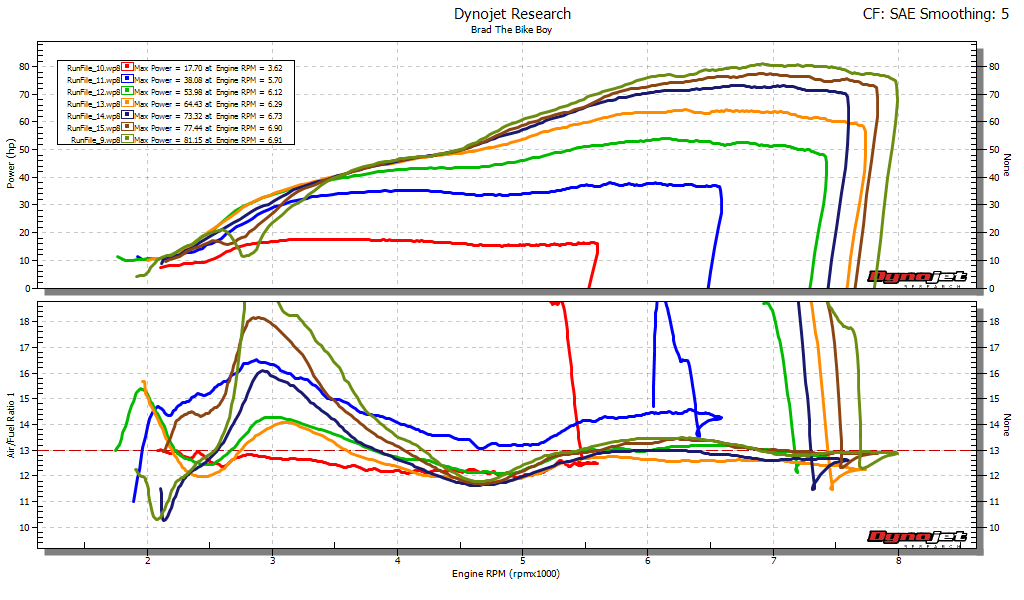
With the 175 mains it came in with it would kill the engine if you held it open from 4,000 rpm - at 6,500 to 7,000 it would shut down, then come back. As the plugs were very black I figured it might be momentarily fouling the plugs. The dyno showed OMG rich - off the scale (under 10:1) by 3,500 rpm. 148 mains fixed it, but the mixture tapered in a straight line from 14:1 around 3,500 rpm to 12:1 by 7,500 rpm.
My suspicion now that I look at it is air bleed sizing, which is not adjustable in Dellortos. So I was worried that I might see a similar thing with the Sport 1100, but also curious that the fact these carbs were made to suit this engine size and rpm range may mean they were different internally to whatever variant of PHM40 was on the Magni. The problem of "the things you don't know you don't know" means sometimes you have no answers. I don't know who you'd ask either.
Red is 175 main, blue 165, green 152, dark blue and yellow 148 (LH and RH samples). A compromise is all that was available here.