Sunday, November 8, 2015

Ducati main bearing failures

I rebuilt an ST3 engine a couple of weeks ago due to a bad main bearing.  I didn't video that one beforehand, but I do have a little video that shows the noise they make well.

The bike in the video is an M400 with 22,000km on it.  The owner had bought it in a private sale, been on several rides with his mates, and was generally happy with his bike.  It wasn't until he took it to someone for a service that he first heard the phrase "WTF is wrong with that!"  A bit shocked by this, he then headed to Ducati City at the recommendation of the someone to see what they thought.  They too asked "WTF is wrong with that!"  Because Ducati City won't deal with the grey import bikes, they sent him to me.  I heard it pull up out the front, with the noise making my skin crawl so badly I had to go out and turn it off.  The high idle wasn't helping the horrid noise either.  This is what it sounded like.


Luckily for the owner, I found Michael at AdrenalinPB had a second hand engine.  We popped that in, and all was happy again.

The ST3 I mentioned at the start was in for a service, and when I fired it up afterwards I had a feeling it was noisy.  It had around 42,000km on it, and 1,500km later it had gone from a bit of a noise to what the video shows (it might have been a bit worse).  It took about $6,500 (including some Pistal high comps and a head reco) to make it quiet again.

I had an S4 Monster in for some work last week, and when I fired it up I heard the dreaded noise again.  It had around 15,000km on it.

I've heard of quite a few MTS1200 doing it around the 20,000km mark.  This is a bit surprising as the 1198 or Diavel don't do it, and theoretically they're all the same thing bottom end and production wise.

The cause is usually the inner race of the RH main bearing pitting.  Sometimes the balls and then the outer race pit as well.  I guess it might depend on how long you let the noise run for as to how far the damage travels.


.

Sunday, October 4, 2015

Ducati: Rotation sensor failures of a new kind

I've had two bikes in over the last couple of weeks with rotation sensor failures.  By rotation sensor I mean the sensor that tells the ECU the engine is running.  It gets called all sorts of things - crank angle sensor, speed sensor, stuff like that.  On the single pick up bikes, which began with the 1.6M ecu of 1995 and continue now with the 59M and 5AM, the sensor was originally in the LH engine or alternator cover, just at the front top edge of it, and triggered by the teeth on the timing gear.  As per the red circle in the photo below.  On the water cooled engines it's hiding behind the hose from the thermostat or lower radiator.


On the 1098 and later engines it has moved to the top of the crankcase just to the rear of the engine mounting bolt hole above the red circle above.  It is still triggered by the timing gear.

Usually, when they fail, the bike stops.  It might start again after it has cooled down a bit.

The first to arrive was an ST3.  It would idle, but not rev without popping and banging.  It arrived at the end of the day, so I took a little time to have a quick look see.  It sounded very rich to me, so I checked the fuel pressure.  It was a little high at 3.5 bar, but nothing outrageous.  The diagnostic tool showed no errors, and all the sensor inputs were totally plausible.  But with the engine running, the RPM was showing 0, which made me think rotation sensor.  Given it was an ST3, and both side fairings had to come off due to the sensor being on the LH in the alternator cover, but the connector being zip tied to one of the RH frame rails, it got put to the side as it was late and I didn't have time to start pulling it apart.

The next one to arrive was an M400ie.  Exactly the same symptoms, which surprised me, but also picked my interest immediately.  Again, it arrived at the end of the day when I had finished what I had planned, so I had time to try the theory.  Being an M400ie, the rotation sensor is in plain view meaning the swap test was simple.  I measured the gear depth, measured my test sensor and popped it in with the original shim.  Started instantly, and ran well enough to confirm the theory.  It took a while for it to clear itself out, no doubt due to the residue of a heap of partially burnt fuel.  But a road test showed it to be fixed.

I ordered a couple of sensors, and when they arrived pulled the sides off the ST3 and replaced its sensor.  Thankfully, that was all it took, and it was ready to go again.

So, a new one on me, but an interesting one to see.

Saturday, October 3, 2015

Chucking something in the bin

I said goodbye to an old friend and faithful companion this week. Bought to match the yellow Guzzi Sport 1100i, we had a lot of fun times together. And the two best rides I'll ever have. Three crashes - Sport 1100i just up the road from the Camberwell house and Philip Island and the KR1S at Sandown. It became my test ride helmet after the YES I was using got damaged in the Monster road test crash. For some reason, one day it just got rather uncomfortable, and into the bin it went.  


Sunday, September 6, 2015

Another great story on inlet manifold length and testing variations thereof from Emerald 3D

.
Yes, it's car based, but it has lots of comparison dyno graphs.  Great back to back test info.

Emerald 3D


Friday, August 7, 2015

Ducati 900 Carb models with and without airbox lids

.
There's a thread going on ducati ms in the Supersport forum about airbox lids and noise and the usual resonance design stuff that comes up, so I thought I'd put up some graphs of lids on and off and snorkles in and out.

For a start, from this post: http://bradthebikeboy.blogspot.com.au/2012/07/carby-model-ss-and-monsters-airbox-lids.html , an M900, std airbox lid and jetting, some sort of slip on muffler.  Blue is snorkles in, red snorkles out.  How it looks is how it felt.


M900 with jet kit (Factory Pro from memory), initially it had 145 (maybe it was 140, I forget now) main jets to start with, then it got 150 and finally 155 I think.  Anyway, green is 145 (or 140) mains and open lid, red 145 (or 140) mains and lid on with snorkles, blue 150 mains and open lid.  No air fuel ratio back then.


Minnie the M600 with standard and open lids, no other changes.  Was running 900 cams, std jetting and Megacycle mufflers.  Blue is std lid, red open lid.  Pretty obvious.  This result is consistant for any of the carb models when running std jetting.


750SS with jet kit tuned for open lid and slip on mufflers.  This bike was running 140 main, which were possibly on the too big side anyway.  Blue is open lid, red std lid.


900SS runs (two different bikes) showing air/fuel ratio only, one with std lid and snorkles in red and std lid and no snorkles in blue.  I haven't put up a power comparison as they are from different dynos as well, so there isn't a correlation between them.


To the above graph I'll add two curves form the second graph at the top for the M900.  All std jetting, with and without snorkles.  The Euro spec 900SS and Monster use the same 140 main jets, Y-2 needle jets and 5C19 needles.  So theoretically they're the same, but it doesn't work out that way.  Light blue is 900SS with snorkels, dark blue without, red M900 with, green M900 without.  The Monster is leaner in both cases.


For an SS main jet size comparison: a 900SL with some Staintunes, open airbox lid and a Dynojet kit.  I revised the kit settings a bit and ran it with both 140 and 145 main jets.  As you can see, the 145 mains hurt the power a touch.  From memory (probably 17 years ago), it didn't feel any different on the road.  Remember, the SS needs smaller mains than the Monster.  Possibly due to the SS fairing blocking airflow?  Dunno.


To summarise, my experience with this topic leads me to the following conclusions: 

1/ Any of the carb model bikes will make more power with an open airbox and jetting to suit.

2/ Jetting to suit is in bold because that's the important part with the std Mikuni carbs.  My belief is that CV carbs are upset by the change in pressure differential across them (between inlet and outlet) more than the added airflow an open lid gives.  It's not just a too lean thing, like you get with an injected bike when doing the same mod, as the dynamic behaviour of the CV carb is completely different to an ecu just putting in the same amount of fuel.  But that could be wrong.

3/ Without jetting to suit, with an open airbox they won't rev out under load.

4/ Without jetting to suit, removing the snorkles will produce a pretty much nil result at best, with the power loss due to the leaner mixture offsetting the power increase due to the extra airflow.

5/ With jetting to suit, the difference between std airbox lid without snorkles and open airbox lid is mainly noise.  Being less of it with std airbox lid without snorkles.  It doesn't seem to affect the performance that much.  I don't have any back to back runs to prove (or disprove) this though.  Something to try at some point.

6/ The noise of the open lid really pisses some people off.  Each to their own.  I used to ride Minnie with std mufflers and open lid, so that way she was quiet when cruising and made some noise when on it.

Friday, July 24, 2015

Ducati: The result of aluminium clutch basket and steel plates


When I first saw this 2003 749S at 27,000km, I inspected the clutch and found it had a steel plate set (meaning the friction plate base material is steel, not aluminium) with an original aluminium basket.  But there wasn't a huge amount of wear, and it as still working, so it was left as was.

I saw it a couple of weeks ago at 58,000km and this was the result.  I forgot to take a photo of the plate tangs, but they they were also very worn.  If it was a bigger engine I expect this would have happened sooner.


It wasn't this bad at 42,000km, when I last had it out.  At that point I replaced the pushrod and needle roller bearing due to wear, and I had to do them again with the basket at 58,000km.  Maybe the worn basket and associated movement allowed the pushrod to move around, but it seemed rather odd that it had done the pushrod in such a short time.
.

Friday, July 10, 2015

Further comment on the Ducati ST3 crank slot incorrectly machined.

.
I thought I'd put up a photo to better explain what I was talking about with the incorrectly machined crank slots, using a photo of a crank.

The crank has two slots machined in the end of it to locate the factory locking tool, and you also use these to locate the turning tools. I've never seen these slots machined off before (not once that i can recall), but these ones certainly were. It would either be an error in or damage to the machining jig I expect. I doubt anyone made the decision to machine them 10 degrees off, as it would be a simple production process.


In the pic you can see the two slots for the tool (red arrows), the alignment slot used to align the flywheel dot (yellow circle) and the timing gear keyway (green circle). The timing and cam pulleys appeared to all be correctly aligned, but I don't recall if this bike had a timing window to see if the flywheel marks lined up with the pointer, or if it was one of the later threaded plug covers. I would expect all these slots would be machined in pretty much one pass though.

As a consequence, using the factory cam timing tools would see the crank locked in the wrong place.

The only way you would know is by doing what I did, so it's not something that would come up often. Using the tools as intended would see this result, but it would be unintended and unknown. The assumption that the tool is right is the assumption you work with when using any tool pretty much, unless anecdotal evidence shows you otherwise. This is the first anecdotal evidence of incorrectly machined slots that I have seen.

Saturday, July 4, 2015

Thin base gaskets for Ducati 996


I recently had some thin base gaskets for the 996 laser cut locally.  I sourced some 0.20 and 0.25mm shim sheet, and the laser cutter had some 0.30mm in stock, so now I have quite a few of each in stock.  Unfortunately, the laser cutting process has left quite a bit of flash on one side, so I'm a bit disappointed in them not being overly saleable as is.  Especially as I have to charge $27.50 each for them.  But I now have a source of them, so if anyone wants any, they're there.

I fitted some to an ST4S engine I was rebuilding (the catalyst for getting them cut) and the 0.20mm thickness gave 1.00mm squish.  Some will need the 0.25 or 0.30mm.

Ducati ST3 front sprocket incorrect position and other wierdness.


I had an ST3 in this week for a big service, and found a few things along the way that made me wonder if I was doing it right.

First of all, it had no opening clearance on 5 of the 6 valves.  Coincidently, it was the horizontal exhaust opener that had clearance, which is also the one I have seen with no clearance on a couple at around this many km (40,000) previously, requiring replacement of cam and rocker.  But this one was ok.

I checked the vertical first, and with all valves having no clearance, I was starting to wonder if I was doing it right frankly.  There wasn't excessive drag on the cams, such as you get when the valve is receding and the closing spring is forcing the rocker onto the cam and wearing both (as seen previously).  It was more like they'd been set that way.  The closers were all around 0.25mm, so all round it was pretty crappy.

The ST3 inlet valves have very soft closing springs, so you can easily force a 'too thick' feeler gauge in between the rocker and opening shim when checking the opening clearance without really noticing it.  I gently lever the closing rocker up with a screwdriver to make sure the valve is closed while checking the opening clearance, just to make sure.  I do the same when checking the closing clearance to get the zero setting on my dial gauge.  For a model allegedly combining the best of 4V performance and 2V maintenance cost, I find the ST3 the most annoying to do valve clearance adjustments on.  Apart from the somewhat crappy access to the vertical exhaust, the ST4/S is easier imo.

Another thing I've noticed valve clearance wise on the ST3 is that some of them (but not a consistant early vs late or the like grouping) need a total combined inlet clearance of 0.25mm (0.010", or 10 thou), or you can feel the cam binding as you rotate it.  Usually I use 0.10mm (4 thou) on both inlet opening and closing, but some of them need 0.13mm (5 thou) on both to stop the binding.  No idea why, just something I've seen.  The exhausts seem happy enough with the usual opening 0.15mm (6 thou) and closing 0.05 - 0.07mm (2 - 3 thou) though.

Given the owner had commented about the bad tune up at its last service (done somewhere else), and this was an early ST3, I thought I'd check the cam timing.  It's a fairly quick job, but it's something owners will often see no benefit in them paying for, so I don't do it as a matter of course.  But this time I sort of had a feeling I should do it.  I find it quite surprising how often my "probably should do that" urge leads to a "wtf" moment and subsequent fix.

Again things turned to weird fairly quickly.  I use a Vee Two engine turning/degree wheel holding tool, and with it TDC for either cylinder is with one of the handles either vertical or horizontal.  This is because the two slots in the end of the crank are machined in the same place on all cranks, and these slots are used by the factory cam timing tools to lock the crank.

Except for this one.  This is what I got:


The slots are 10 degrees off (retarded), something I've never seen before.  I rechecked my TDC (done using a piston stop), but no matter how hard I tried to find a mistake, I couldn't.  Even the visual "watch the piston move" test showed it was about right.  So I submitted to the reality and moved forward.  The 10 degree offset didn't really correspond to the vertical cam though, which was -7/79 (133 degree inlet c/l) at 1mm lift, or 19 degrees retarded.  I don't think the factory tools would have it 9 degrees off (allowing for the 10 degree slot error), but could be wrong.  Actually, just checking my old ST3 cam timing report, it was 123 or 9 degrees retarded on the vertical as delivered.  Anyway, it's now at 113 degrees, or 1 degree advanced.

The horizontal inlet was 9 degrees off (retarded), which is consistant with the crank slot error.  Now it too is at 113.

From there on the set up was pretty straight forward.  I redid the TPS baseline setting (was 110mV), and 2.3 degrees via the diagnostic tool was actually 337mV.  I wound one of the air bleeds in quite a bit from where it was, with the running balance ok, and the idle trimmer went from +5 to -5 for 5% CO.  Seemed to ride like it should, hopefully the owner will be of the same opinion.

The next issue is one that I have seen before.  I had a 2006 ST3 in sometime ago that needed chain and sprockets.  I removed the front (countershaft) sprocket and found the chain had been wearing on the head of the oil gallery plug (an M6 cap head screw) behind the sprocket.  Assuming this wasn't meant to be happening, I had a bit of a look-see which showed offset wear (to the inside, or RH) on the chain slider on top of the swingarm and came to the following (longwinded) conclusion.

When they introduced the 916 in 1994, the gearbox output shaft had a new part # as compared to the other big block engines (900, 906, 907, 851 and 888).  Later, when the M900ie appeared in 2000 with the "748" close ratio gearbox, it had a front sprocket that has the teeth centred pretty much, instead of being offset to the outer (LH) edge.  The offset was 5mm, which as it turns out is how much longer the "916" series output shaft is compared to the 900, 906, 907, 851 and 888.  This longer output shaft was then used in pretty much every new model, the next of which was the ST2.

When the Testastretta appeared, with the dual row ball bearing supporting the output shaft behind the front sprocket and large nut holding the front sprocket on, it too took on the longer output shaft positioning for the sprocket, as that's what the chassis required.  To achieve this, there is a spacer/seal runner behind the front sprocket that is pulled up between the bearing inner and sprocket by the nut and its 190Nm.

This spacer is the same thickness on all the Testastretta models, and when the Monster series was revised in 2001 (S4) and 2002 (900) to the ST based chassis, these big block models used the 5mm longer shaft as per the ST4 and ST2 they were based on.  In 2003, the 900 became the 1000, with the Testastretta's bottom end and therefore front sprocket location method.  For the M1000, being based on the ST, there was no sprocket alignment issue as its chassis was designed around this front sprocket location.

However, the 1000SSie chassis was still that of the 900SSie, which itself was much the same as the 900SS from 1991.  Including front and rear sprocket location.  So, with the Testastretta based bottom end, the 1000SSie required a 5mm thinner spacer/seal runner to move the sprocket in 5mm to replicate the 1991 - 2002 position.

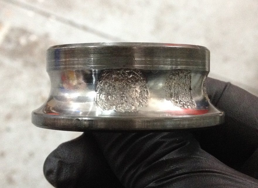
This gives two spacer/seal runner part #, being 71312041A (1000SSie) and 71311571A (everything else, supersedes to 71313931A)    And, as usual when there's two of something, inevitably the wrong one gets fitted somewhere along the line.  For these spacers, that appears to be the ST3.  The part I'm talking about is # 13 in the diagram below.


The photo below gives the first visual clue: the length of output shaft protruding through the nut.  It's more than I would expect to see on anything other than a 1000SSie.


This bike is a 2004 model, so there's no oil gallery plug behind the sprocket for the chain to wear away.  But the offset wear on the chain slider on top of the swingarm was as expected.  If I put my little laser chain aligning tool on the side of the front sprocket and aim it at the rear sprocket (assuming the rear is in about the right place), you will see the laser dot hitting the sprocket teeth.  It should be hitting the outer plate of the chain.

To solve this, we need to move the sprocket out 5mm.  Typically, either spacer/seal runner part # is ex Italy, giving the obvious option of machining a 5mm thick spacer to go between original spacer and sprocket.  This presents a problem of suitable material at hand, as it needs to be 25 x 35 x 5 and steel.  I'm rather suss of making this sort of thing from aluminium, especially when it gets 190Nm of squash on it.  The first time I used an old nut (possibly primary drive) narrowed to the right thickness.  This time I went on the scrounge to the fencing place just up the road (often useful), and found some big arse gal nuts.  From one of these I turned up the required spacer and all was good again.  I'm going to back order the correct part for stock, just so next time i have what I need at hand.

As to whether or not all ST3 have this issue, I don't know.  I've not heard of it before (see below), and it's the sort of thing you only notice when it causes something noticeable.  The 2006 model with its oil gallery plug gave me something noticeable, but the 2004 wouldn't have made it obvious.  From now on, I'll look at every ST3 I get in.

**A quick google shows others have noticed unusual wear, but I don't think anyone else has come to this conclusion.  Sample size is what brings the anecdotal evidence, and that's easier for someone like me.

Saturday, May 2, 2015

"Do you really want to know about expansion chambers"


A great technical article by Gordon Jennings from way back in the day. Allow an hour or so.

Do you really want to know about expansion chambers

Friday, May 1, 2015

Ducati 888 SP4 charging system issue and influence of bad fuel pump.


I had a customer drop in this week with his 888 SP4.  The charge light on the dash had been coming on and staying on above idle, and the rpm required to make it go out was getting higher and higher.  A voltage check at the battery showed it struggling to get to 13 V at 5,000 rpm, so clearly something was wrong.

I did the usual checks, and with a rectifier connected directly between alternator and battery to check the loaded potential alternator output (unregulated), the most it had was 13.1 V.  Usually, you give it a quick rev, watch the voltage go to 15 - 16 volts then shut it down before the battery throws a hissy fit.  Sadly, 13.1 volts was not going to induce any hissy.  Well, not in the battery anyway.

I tracked down a new alternator at Frasers in Perth, which was air bagged over and fitted.  Unfortunately, the old alternator looked great, something of a bad omen as it turned out.  I ran the rectifier test again, and this time we had a mind blowing 13.5 V.  This made me rather sad, and very perplexed.  I tried another battery just in case, using one of my spares that had been charged the previous week.  You need to make sure you have a fully charged battery fitted when diagnosing charging faults, but even with this fitted there was no change.

The 851 and 888 SP use the single phase "narrow" alternator, the same as that fitted to the 350, 400, 600 and 750 engines pre 1998 (and 900 until mid 1992 or so).  The normal 851 and 888 use the "wide" alternator, also fitted to the 906, 907, 1993 on 900 and the later 748 and 916.  I had a stator only in a box with the wide part #, but I couldn't find the complete wide alternator I have (I saw it in a box a month or so ago), so I wasn't actually sure what was in the SP until the new one arrived and the old came out.  The photo below, which I stole from an Ebay ad, shows a wide rotor single phase alternator.


Turns out the wide stator is the same width as the narrow stator, with the steel part of the stator being 30 mm wide.  This fits with the Electrexworld listing showing a 30 mm stator (which again was confusing me).  But, the rotor is wider.  The narrow rotor is 30 mm total width, and the magnet section is 24 mm wide.  The wide rotor is around 40 mm wide I believe.  I don't actually have one to hand to measure (it's in a plastic crate somewhere), but it's something like that.

Given that I had a maximum of 13.5 volts, I figured I'd best go looking for the rest, if indeed any more existed.  This is the same alt used in a 600 or 750, and I have seen them go 14.3 V regulated easily, and much higher when running through just a rectifier.  I was struggling to think of places for the extra to go.  I tried lights on/off, which gave a steady 0.2 V change.  Most things will drop and then recover the voltage when you turn the lights on, but a drop and no recovery meant there wasn't anything more to be had.

The main difference I could think of between an M600 and an 888 SP4 is that the SP4 is injected.  So with it running and the tank raised, I popped the fuel pump connector and watched the battery voltage as it ran down to a fuel-less stall.  A 0.4 V increase to 13.9 V showed a potential worth pursuing.

This bike has only done 9,000 km in its 23 year lifetime, but the fuel filter was dated 06 from memory, indicating it was 8 - 9 years old at most.  The little round yellow filter on the bottom of the pump was damaged, with a few holes in the bottom section.  Given there was quite a bit of loose debris in the bottom of the tank, it had possibly been sucking grit even though the pump had a steel mesh screen on its entry.  The fuel filter (a KL145 in this 1992 model) was so blocked that I couldn't blow through it at all.  Along with the filter I replaced the hoses with some R10 spec and assembled it enough to try it again to see how many volts I'd found.  The result was maybe 0. 05, summarised as pretty much none.

At this point I was running it with the regulator connected again, so we had around 13.2 volts at the battery up at 4 - 5,000 rpm.

The SP4 has a "small" pump (not the larger pump of the 1992 and prior bikes), which is replaceable with the California Cycleworks FP-916.  Originally a Walbro pump, it does have individual electrical spade terminals (earth narrower than +ve), unlike the later style replicated by the FP-916 which has two spades the same wide carried in a black plastic connector block.  I cut a black plastic connector from a dead fuel level sender (never throw anything out!) and rigged it to work for a test.  Just turning the key on produced a pump sound very different to the previous, and firing it showed 13.6 V at around 4,000 rpm.  Switching the lights on gave the expected (hoped) drop and recover, and it would hold 13.6 V no matter what.

So I swapped the terminals on the pump power wires to suit those required by the black plastic connector and fitted the pump into its hole for the last time.  The 1992 models use the same rubber pump holder as the 916 series, but it goes into a round holed steel plate holder in the tank, with ridges moulded into the rubber holding it in.  It's a complete bastard to remove with little access behind it, and even my nitrile gloves were getting holed and filling with petrol in the end, which I really hate.  And the tops of my forearms, having been rubbed against the underside of the tank cap recess repeatedly, were quite red and angry.  But, finally, it was back together and I was much relieved.

The charge light was now not showing at all, even at idle, and a stable 13.6 V, while less than I like to see, was better than what it had when it came in.  The voltage drops in the loom between regulator and battery were about 0.15 V total on both +ve and -ve, pretty impressive for a 23 year old wiring loom.  I often see up to 1 V in bikes 10 years old.  

While the alternator itself didn't fix the issue, it was certainly partly to blame.  But it still was an expensive half fix.  And the impact of the fuel pump issue on the battery charge voltage is something I haven't ever seen before.  Most of these charging systems, with a good regulator and wiring, will knock out 14.1 - 14.3 V all day every day.  People like to give the old SP alternators a bad rap total power wise, but I was amazed to find it actually offering so little maximum output voltage in an unregulated test.  It really did stagger me, to the point of thinking there's still something I am missing.  But, I did learn quite a bit over the course of a rather frustrating day, and that's always a good outcome.

Saturday, April 18, 2015

Helibars clip ons on a 748 / 916 / 996 / 998

I had a customer who wanted some higher bars on her 748.  I enquired about a few of the options, and came across the Helibars TS07026 clip ons.  Available locally, they're at the expensive end of the range at $480, but they come as a guaranteed straight fit.  They have the holes drilled for switch blocks, meaning you don't need to mess around with that (always an annoying part) and the labour time it entails.  Once fitted the only clearance issue I noted was between the tops of my fingers and the mirrors at full lock, and that was more a surprise touch than real issue.

I fitted the LH side, and took a photo from behind for a comparison with the std RH side.  With a very obvious shallower angle, they're advertised as 44mm higher, 25mm further back and 30mm wider.


The only issue I had fitting them was with the front brake hose.  It did seem like it was too long anyway, but the angle of the banjo meant that I was very limited in options.  Running forward as shown, it looked a bit odd, but cleared everything and didn't get jammed at full lock.  The instructions (which I forgot to read until I was done) specified running the throttle cable under the front brake master cylinder.  The drilled hole in the handle bar for the throttle housing locating pin would have required this, but the housing on this bike was pinless.  And over the top seemed more natural when I was lining it all up.


To further help with the comfort, I pushed the forks down through the triple clamps 13 mm (they were at the specified setting) so that the tops of the tubes were flush with the top triple at the inner edge.  Then, in the rather futile hope that the rear suspension rod rose joints would actually move in the rod, I removed the rod to try to adjust it.  It was at 262 mm centre to centre, and after much heat and Inox I finally managed to get one end to wind in to give 259 mm.  This gave us a 10 mm drop in ride height at the rear axle.  Overall, this combined 23 mm change in attitude rotates the bike approximately 1 degree.

The owner found the most noticeable change to be in the angle of her neck, which combined with the general reduction in forward weight will hopefully see her enjoying the bike more regularly.

Sunday, March 8, 2015

Ducati Supersport mufflers carburettor models vs ie

I took some photos of Supersport mufflers to give a comparison of what will fit what and how.  The models compared here are 1990 to 1997 900SS (carburettor) and 1998 - 2007 620, 750, 800, 900 and 1000SSie.  All the SSie mufflers are the same.  The 1990 to 1997 900SS mufflers are the same as the 851 from 1989 onwards, so they're more correctly 851 mufflers.  The 888 mufflers also fit, and I believe they were fitted to some 900SS/SP that went only to the USA (generally).

As a note, the 1991 - 1997 750SS mufflers are unique, due to the header pipe size.

The 851 muffler is 100mm diameter, the 888 muffler 110mm from memory, and the 888 muffler doesn't have a removable end baffle like the 851 muffler.

In this comparison, we have a Ducati Performance (by Remus) muffler to suit SSie at the top and a polished 851 muffler at the bottom.


SSie muffler fitted to 851, as I didn't have a 900SS to hand


851/900SS muffler fitted to 750SSie.  The muffler was almost touching the swingarm at the leading edge of the canister.


Top view of SSie muffler (bottom) on 851, showing how much longer they are overall.


Friday, January 16, 2015

Photo of that peg-bracket to swingarm support idea

This is on the SS.  I'm sure I had used them on an SS before, but it certainly didn't line up.  Maybe the lower holes are for the ST series.  Top holes worked for Minnie, where they have been used before.  Definitely been on two of my bikes, and I've only owned this one SS.  888 and ST2 also had engines out, 888 and Monster should be the same.  It has an aluminium spike on the other side going into the swingarm.

I also worked out the photos are cloudy because my iPhone lens was dirty.