.
A member of the 851 Yahoo list Posted a link to Bob Brown's 851 race bike that is currently for sale on Bikepoint: 851 Racer. I've seen the bike in person and think it's pretty cool, so I thought I'd put a little bit up on it.
Originally an 851 kit, it had lots of mods over the four or so seasons it was raced (88 - 91). Bob had cylinders made up to allow it to go to nearly 100mm bore for a full 1000cc, and the frame had extra bars welded onto each side of the vertical cylinder that Bob says made a big difference to crankcase life. It cracked a few sets early on, as did all the 851 that were raced. Roche used 36 engines in 1990: Bob witnessed the last one letting go rather impressively coming on to the main straight in the last race of the season at Manfield, after he'd won the title in the first race of the day. From memory the 916 wasn't any better, I'm sure Corser and Fogarty used a similar number of engines in the mid 90's.
Duane Mitchell, who worked with Bob in the era, told me years ago it was very quick, and went past the factory bikes with ease in a straight line. Until it just shut down, which it apparantly did with monotonous regularity. So they pulled the Weber injection and Bob had some manifolds cast to fit a pair of FCR39 to each cylinder and a custom alternator cover to allow a Krober ignition to be fitted to it. Which made it much more reliable.
It's obvious how much time and money went into it, with lots of very cool period race bits like radial master cylinders, etc. And lots of custom/one off work as well. Clearly a money pit, and very cool.
He also has his new in glass case 851 Tricolore Kit listed too: 851 Tricolore Kit
And also this TT2, which was displayed a few (several) years ago at the FOIM at the Museum. It's just gorgeous: TT2
.
Sunday, December 16, 2012
Friday, December 14, 2012
Keihin FCR main air jet test: post 2
.
I was going to put more info in the other night, but it was late and I had work to do.
The graph below shows three different bikes all running the same 152 mains (just can't get rid of them) and how the curves taper (or don't). Blue is M750 with FCR39, Red 900SS with FCR41 and green 900SS with FCR39. The green curve is by far the most consistant.

It also seems that the richer my M750 gets, the less consistant the WOT mixture becomes. In particular, the more prominent the (comparatively) lean peak at 7,200 becomes. Blue is 152 mains, red is 158 mains and green is 165 mains. Also, the three step richer change from 158 to 165 has a much bigger impact on mixture than the two step 152 to 158 change. I have done a few FCR main jet changes that have struck me as having less effect than I anticipated.

Although, the Mikuni 600 and later 900 carbs I had previously been running on Minnie could also show a lean peak at similar rpm depending on inlet and exhaust configuration.
I also ran some part throttle checks. Initially when I fitted the FCR I tried 52 pilots, then went down to 48 after the first ride and down to 45 before the last dyno runs to try to cure the 1/8 or so throttle richness. It's possibly still a little on the rich side. I have left the idle mixture (slow fuel) and slow air screws at their spec settings, just because they seem to be a bit more stable that way in my limited experience. And some playing with them didn't seem to help.
The next graph shows 1/4 throttle, which has remained surprisingly stable. I say that because both pilot and main jets have been changed, and I'm told that the main does have an impact on part throttle. So I'm not sure if the return to smaller mains will have an impact on the 1/4 throttle mixture. Hopefully not. Blue is 52, red 45.

1/2 throttle shows a richer mixture with the larger mains, blue 158, red 165.

Similarly, 3/4 throttle also shows a richer mixture with the larger mains, blue 158, red 165. The sudden step at 4,000 rpm is a bit wacky too.

Given Minnie is now unregistered, I won't get to try out any more changes. But I think I'll set the FCR up with 160 mains instead of the 158 and leave all else as was. Hopefully the jetting will work ok in an SS, as that's where the engine is theorectically going.
She was running very nicely, although the 1/2 throttle wheelies when taking off from the lights were getting a little too easy and frequent. Started well too with the "two pumps, wind in idle speed screw, press button" procedure.
.
Wednesday, December 12, 2012
Keihin FCR main air jet test
.
Today was Minnies last day of rego, and at this point of time I'm not planning to re-register her for the minimal use that she gets. But I had one test I wanted to try with the FCR, and that was larger main air jets.
The idea is that the main air jet sizing wil influence the shape of the fuel curve. Read Patick Burn's tuning guide for a much better explanation. I have found that with the FCR on Ducati engines you often get a mixture that tapers rich as rpm climbs. Specifcally it seems to be with larger carb size to engine capacity ratios. Or, more simply, 41 on a 900 as compared to 39 on a 900, or 39 on a 750 compared to 39 on a 900. Comparitively, the 900SS I fitted FCR39 to gave a relatively flat curve.
The FCR for Ducatis come with a 200 main air jet, the largest Keihin make. So the assumption was I could get some 200 and drill them out. As you do. With my jet drill kit the 200 was between 1.90 and 2.00mm, and I drilled them to 2.10mm. I also went up to 165 main jets from the 158 that I had fitted previously on the assumption that I'd need more fuel. Turns out, perhaps, that the reason the biggest main air jet available is 200 is because that's as big as the carb will respond to. That's the theory I'm running with at this point, based on tody's runs.
If I told you the graph below was for 158 mains in red and 165 in blue you'd probably believe me. I would. Same shape, just richer. So, no joy in main air jet land, but at least now I know. And that has to be worth the effort.

Now I have to put the 158 mains back in, and probably some undrilled 200 main air jets, just to be sure.
.
Sunday, November 25, 2012
Charging system diagnosis procedure
I replied to a forum post somewhere regarding how I diagnose charging system faults, and I thought I'd best copy it to a word document so I could simply copy and paste if I needed it again. Then I edited the mistakes out and figured I might as well just post it here. I hope it helps de-mystify the process for some. I'm not overly electrically minded, but as with most diagnosis it's simply fault finding by process. I find that I only ever get into trouble if I rush and forget the procedure.
There's now (May 2023) a video on my Youtube channel too - Charging system diagnosis
Following are the checks
I do.
Visual:
Check regulator - the single phase Ducati (2 yellow wires) often leak black goo or have large holes in the back of them. 3 phase Shendengan generally don't.
Visual:
Check regulator - the single phase Ducati (2 yellow wires) often leak black goo or have large holes in the back of them. 3 phase Shendengan generally don't.
Check yellow wires from alternator for melting and connector burning. The 3 pin white terminal will melt if used as a two pin connector on a single phase system as per the upgrade kits. Almost guarantee it. Moto Guzzi Breva 750 among other models also use this white connector with a Ducati Electronica single phase system, and I have seen them burn similarly.
The yellow wires often get green
corrosion on them under the insulation, which has usually turned whitish and
brittle. I tend to cut it back until it's nice and new looking if possible,
but it's not really necessary ime.
Check other wires out of regulator to battery.
Check maxi fuse.
Battery:
Charge with a real charger (not a trickle charger) and load test once charged. If it won't hold load, replace it. You need a fully charged battery to diagnose the system.
Multimeter:
Check for continuity between the two or three alternator wires. Should have some with very low resistance. For clarity lets say 0 ohms.
Check for continuity between alternator wires and ground. Should be none.
Check for continuity between the regulator output positive (red) wire and the battery positive terminal. This will also show up a blown maxi fuse.
Check for continuity between the regulator output negative (black or green) wires and the battery negative terminal on the 3 phase systems, or between the regulator body/earth wire and the battery negative terminal on a single phase system.
Check alternator AC output between yellow wires. This test is carried out with the yellow wires from alternator to regulator disconnected. Hook the multimeter leads into the two (or two of the three) yellow leads from the alternator with meter set to AC and read the voltage. It should get to 70Vac fairly quickly. On a 3 phase system check between all combinations of two yellows. Realistically, this is a potential voltage, not a real voltage. Do the dc test below to see if it is actually capable of making voltage.
Fit a dc rectifier between the yellows and battery. This directly charges the battery, and will show you whether or not the alternator can produce under load, which the ac test doesn't. Battery voltage should climb over 15v at quite low rpm. Don’t hold it above 15v for too long, but certainly make sure it can get there. I usually raise the rpm until I see 16 or 17, and then shut it off straight away.
If everything so far has passed, replace the regulator.
Other info
I always use round bullet terminals for the yellow alternator to regulator connection in the same size as the originals on the Ducati single phase systems. They’re very reliable if kept clean and lubed. Do not use flat spade terminals for the yellow alternator to regulator connection on a single phase system. Even when not in a connector, I’ve never seen them last. Always cover the alternator to regulator terminals with heat shrink too. Pretty much lube every terminal and connector, and heat shrink all bullet or individual terminal connections.
Some people like to solder the yellow alternator to regulator wires together instead of using connectors. I don’t, as it’s something you can’t undo and reconnect easily without the correct tools if you have to. The round bullet terminals are so reliable I see no point.
Once you've replaced the regulator, check the voltage at the battery with the engine running. You should get 14.3 or so v.
If not, (I always do this check anyway) check the voltage drop between the regulator output positive (red) wire and the battery positive. This will show you how much voltage drop there is in the wiring loom (including the maxi fuse). It’s common to see 0.5V and sometimes more here.
Do the same check for the regulator output negative (black or green) wires and the battery negative terminal on the 3 phase systems, or between the regulator body/earth wire and the battery negative terminal on a single phase system. This is usually much lower, but again definitely worth checking.
I often run a jump wire on a single phase system from regulator body to the
battery negative terminal and check the battery voltage with the jump on and
off. This will tell you if the earth at the regulator body is bad.
If you get voltage drops I run extra wires from the regulator to the battery. Given I always replace single phase regulators with the 3 phase Shendengan SH579 that is fitted to the 3 phase bikes as std (just cut one of the yellows at the regulator short under the sheath and leave unconnected) you don’t need to earth the regulator body. But if there is a wire there you might as well fit it to a mounting screw. Saves people seeing a wire dangling and thinking something is wrong. Just run extra earth wires from the regulator 4 pin connector (2 greens are earth) back to the battery. I usually go to the frame ground point as well if it’s on the way, such as on a pre 2002 Monster. Just make sure you scrape the frame paint off and grease the terminals and frame.
For the positive wires I run from the 2 red wires on the regulator 4 pin connector back to the maxi fuse (using new terminals) and from the maxi fuse to the battery. People who know more than me about this stuff say there’s no need to include a fuse in this circuit, but I like to keep it if I can (i.e., have the right terminals)
This way you end up with one more terminal per post at the battery, but sometimes you pick up more voltage than you’d expect. With a good regulator, a good battery and fresh wiring I always see 14.2 – 14.3V at the battery.
I leave the old maxi fuse terminals connected, just cover them with heat shrink and zip tie out of the way. Same with positive (red) and two wire flat connectors that went to the old single phase regulator. That way the loom is still original as some people like them to remain that way.
Note: With the SH579 you lose the battery light on the dash. This upsets some people.
If you use an original style or Electrex or other single phase regulator that uses a reference voltage input (the two wire flat connector has one wire to run the light, the other is a reference) then you need to make sure the reference is accurate. This reference is switched through the ignition switch and runs through the loom. If the reference is low, due to the resistance that naturally builds up in an old loom, the regulator will think the battery voltage is lower than it actually is and it will overcharge the battery. I think it’s the white/red wire (or maybe pink?).
You can either check the voltage in this wire or (better) run a jump wire from the battery positive to the connector. I pull the connector apart enough that it’s still connected, but you can touch the terminal. Then, with the engine running and while checking the battery voltage, touch the jump wire to the terminal. If the battery voltage drops instantly (and it will if it’s overcharging) the easiest fix is to cut the reference wire on the loom side of the two wire flat connector, fit a relay running battery power direct to this wire into the regulator and switch the relay on with the loom side of the reference wire coming from the ignition switch. 906 Paso have done this for years, and I’ve seen a few Monsters and SS do it.
The SH579 3 phase regulator doesn’t use a reference, so fitting one does away with this potential issue.
I've not used a FH series Shendengan mosfet style reg yet, but only because I haven't actually got to order any. I keep meaning too. The Multi 1200 uses a mosfet reg.
.
Tuesday, November 20, 2012
Ducati ie models and voltage drop to coils and injectors
.
I had an M800 in last week to check for poor idling which turned out to be closing clearance related. Well, I expect anyway, the owner was going to play with it.
But one of the things I checked was voltage at the coils. The horizontal coil is easy to get to, just under the back of the airbox. With the battery at 13V or so, the coil had 11.5. Jumping battery voltage direct to the coil (and therefore into the rest of the little loom that is downstream of the injection relay: coils and injectors mainly) didn't help the idle quality, but richened the mixture from 2.5 to 4.5% CO without any other change.
I have had another M400ie with a similar voltage drop issue, but i don't recall checking the idle mixture at the same time as playing with voltage. It had an ongoing misfire issue (on the horizontal from memory) that I never got to resolve to my or the owner's satisfaction before he got sick of me and went elsewhere. But I'm quite convinced it was related to voltage drop in this area.
.
Tuesday, November 13, 2012
Ducati 900: W heads vs V heads
.
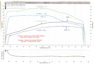
I had a fellow named Wilco send me some dyno runs for his Cagiva Gran Canyon (fuel injected 900 motor) before and after a cylinder head replacement. Originally fitted with the same style heads as the later 90's M900 (W stamp) fitted with the 750 sized valves and 750 OR/VR cams, he had replaced them with some V stamp heads from a carburettor model 900SS running the OHT/VHT cams. The OHT/VHT grind is little smaller than the 900SSie cams that I fitted to a Gran Canyon with std heads some years ago. See http://www.bikeboy.org/grancanyon.html for more info.
As you can see, the bigger valves really help wake it up. It's the result I was hoping to see with the cams alone. Obviously the valves are more important. For a carby model M900 with the long manifolds the top end increase might not be so great, but even if it peaked at 7,000 rpm it is still a large increase.
Thanks to Wilco for supplying the info.

There's some more info in this youtube clip:
Saturday, October 27, 2012
Festival Of Italian Motorcycles 2012
.
http://www.cimaa.asn.au/?p=1320
This years FOIM is on Sunday November 18 at a new location. Actually an old location, the Argyle Gardens on Lygon St, Carlton. I attended the FOIM there a couple of times in the mid 90's, one year riding Trev's Guzzi V7 Special (actually an 850GT masquarading as a V7 from memory, before I had finished my own).
It's a great location, right in the middle of Lygon Street.
I'll be there under my little fold out pergola talking for 4 or so hours and seeing not much apart from the passing faces.
.
Friday, October 26, 2012
New Bike!
.
Well, I say it like I'm all excited. I've actually had it for two weeks and haven't really done anything to it, apart from wonder why I thought it was a good idea.
I have spent some time on Ebay buying bits though. Maybe that's where the enthusiasm has gone. Sucked away like the money from my Paypal account buying another fuel tank to replace the prevously repaired and still weeping original one that has an interior full of nasty. And a standard muffler. When, oh when are people going to realise that standard parts are worth keeping.
Realistically, had the fuel tank repair and condition been listed in the Ebay ad I'd probably have steered clear in the first place. As ever, there's always a reason why things are cheap. At least the frame's not cracked.
Which reminds me, I haven't said what it is yet. An SS. All 400 badass, ball tearing cc of it. A 1993 model, it's actually one of a few genuine Australian import SS Juniors. With 85,000km on the clock it's done its share of work, but hopefully it'll stand up to some riding, and no doubt some dyno runs.
1993 means gold frame and black wheels (unless it's a 900SL or 888SP5, of which it is definitely neither). I dislike black wheels with some passion, especially on 1993 model Ducatis. The 1994 bikes with the gold wheels just look so much better to me.
Unfortunately, 1993 also means 17mm front axle. I was thinking I could just pull the wheels and slot them into Minne, who as a 1997 model has gold wheels. But as a 1997 model she also has a 20mm front axle, and the two are completely incompatible. And swapping the speedo drive with the front wheel won't help either (forks are the same axle hole wise) as the SS and Monster speedos require different drive ratios.
As to intent, well, permission for the purchase was provided on the notion that I could turn it over and make some money. Which, if history is any guide, is something I am simply not capable of when it comes to motorcycles. My thoughts have turned to maybe selling Minnie instead, although to do that and have it be worthwhile Minnie needs to be LAMS again, which means fitting a 600cc engine.
Or an engine inside some 600 cases, using the 750 crank currently inside the engine in her, 620 pistons, 750 heads machined to fit, etc. As if i have time to do that. And it's not exactly in the spirit of the LAMS law either.
Of course that leaves the left overs and other parts on hand to make an 827cc small block.
A photo of it about to come off the trailer. Only one I've taken so far. So my first 'new' bike in 8 or more years isn't really filling me with enthusiasm it seems.
a.jpg)
.
Sunday, October 21, 2012
Throttle Position Sensor setting procedure for Moto Guzzi California and Bellagio
.
I had an email asking about Cali TPS set up, and I'd had this report almost ready to go for some time, so thought I'd pop it up here for a quick view. It will go into the reports at some point of time as that way it's easier to find.


I had an email asking about Cali TPS set up, and I'd had this report almost ready to go for some time, so thought I'd pop it up here for a quick view. It will go into the reports at some point of time as that way it's easier to find.
The throttle bodies fitted to the California and Bellagio are unique to
these two models. They are 40mm bore and
have a link from a central cable wheel out to each throttle blade. So the procedure has a couple of variations
from the other Guzzi models. Generally
the throttle bodies on other models have a cable wheel on one throttle, then a
link from that to the other in a master/slave style relationship. With the Cali and Bellagio throttle bodies
it’s more two slaves (call it a co-op for the socialists among us) so the idle
balance is not influenced by the running balance at all.
The throttle body set up procedure is the same for both the early P8
ecu and later 1.5M ecu bikes. The photos
relate to the later 1.5M ecu bikes with the small round TPS. P8 ecu bikes generally have the large square
TPS, but the concept and procedure are the same.
The photos below have red numbers to denote components and then yellow
numbers and arrows to denote them being used later. Each number is only used once.
All instructions are based on the premise that you have the equipment
required up to and including the diagnostic tools and gas analyser. You may not, and this will influence how far
you can go. Ideally you will go all the
way. It’s always nicer.
1/ Remove the crappy plastic throttle body covers. They can have little cap screws or 5.5mm
(from memory) hex screws as circled in yellow.

2/ The TPS is mounted under the LH throttle body. The photo below shows the air bleed (1) and
TPS (2). The TPS screws are 7mm hex on
earlier bikes or Torx20 on the later ones.
Getting all the yellow sealing paint out to allow the torx fitting to
seat correctly can be a pain.

3/ On top of the LH throttle body is the blade arm pivot point for the black
plastic arm coming from the central cable wheel (3) and the throttle balance
adjuster screw (4).

4/ The throttle stop screw for the LH throttle body (9) is at the rear,
as shown below.

5/ The RH throttle body is much the same, just mirrored. Throttle blade arm pivot point for the black
plastic arm coming from the central cable wheel (6), throttle stop screw at the
rear (5), air bleed underneath (8).


5/ The screw at the central cable wheel is the fast idle
adjustment. It has nothing to do with
throttle balance. Although, given the
little lever at the clutch side of the bars generally won’t stay where you put
it, it often has very little to do with the fast idle speed either.

6/ Back probe the TPS connector to take the voltage across the two
outer wires. You need to turn the
ignition on to power the circuit. In its
original position, you should see 400 – 500mV and up to 4.85V at full throttle. I note the setting just for the sake of
knowing. If you don’t get the required
voltage from the two outer wires you may need to try other combinations, but I
believe that is correct.

7/ To baseline the TPS, disconnect the black plastic arm coming from
the central cable wheel (3) by removing the little C clip. Be careful, as these little clips are
incredibly good at pissing off on you. And
spending half an hour crawling around the floor to find a 20c part is
incredibly annoying. Then wind out the
throttle stop screw (9) until the throttle blade can fully close. I tend to snap it shut to make sure it can
fully shut, but then open and close it more gently to not get a false
reading. Gently closed with a little
force is the best way to get a good base setting. Generally you’d expect to see anywhere from
100 to 180mV. Again, I note the setting
just for the sake of knowing.

8/ Loosen the two TPS screws and move the TPS as required to give
150mV. I always check the voltage again
once the screws are tight, as things tend to move around enough to often
frustrate you.

9/ Once you have 150mV with the throttle fully closed, wind the
throttle stop screw (9) in again until you get the desired voltage for
idle. The manuals give the reading in
degrees of throttle opening, which you read via the diagnostic software. The spec is 3.2 to 3.6 degrees. Nominally, this corresponds to 486 to
528mV. The relationship is mV = (degrees
x 105) + 150. Although, the ecu doesn’t
always read this the same. No idea why. You might set the throttle stop screw to,
say, 486mV, but via the diagnostics you’ll get 2.9 degrees instead of 3.2. Or 3.5.
Just the way it is. I usually go
by degrees, not mV.
In the past I have found variation between bikes from some needing the
stop set to 3.2 degrees or they’ll idle too high to some set to 3.6 degrees and
air bleeds wound out to bring the idle up.
From here in, the LH stop screw is not touched again. Unless you have a too high idle condition
after step 13 or 16. Then you have to
adjust as required to make it work, unfortunately.
10/ Reconnect the black plastic arm coming from the central cable wheel
(3) and refit the c clip (just as easy to lose now as it was when
removing). Check to make sure the
throttle hasn’t been opened at all by this.
The voltage out of the TPS will tell you if it has. If the TPS voltage does change you need to
add slack to the opening throttle cable or back off the fast idle adjusting
screw (7) as required.
11/ Hook up the balance equipment to each manifold and wind the air
bleeds (1) and (8) fully in. I note how
far out they were just for the sake of knowing.

12/ Remove the plugs in the headers and fit tubes to sample the idle
mixture. Didn’t take a photo of them,
sorry. Generally a 15mm hex head.
13/ Start and run the engine until warm. It should idle to some extent with both air
bleeds fully in (chuga chuga chuga).
Because the idle balance is not influenced by the running balance at
all, you adjust the idle balance by the RH throttle stop screw (5) so that you
have equal vacuum on both cylinders.

14/ Now you adjust the running balance.
This is a compromise based on how much variation you get in cylinder to
cylinder vacuum as you open the throttle and increase the rpm above idle. Also remember that you might get to 8 or so
degrees opening at most when free revving it in neutral up to 6,000rpm or so,
whereas on the road you’ll often be above that just cruising. So you’re not getting a full “through the
range” indication – there’s no way you’ll get to even quarter throttle on a
free rev. I just look at the variation
in vacuum between the cylinders and adjust the balance screw (4) as required to
give a best overall compromise. If this
adjustment changes the idle speed then you need to add slack to the opening
throttle cable or back off the fast idle adjusting screw (7) as required.

15/ Next step is to set the idle speed.
Hopefully it’s not too high, so you wind out the air bleeds (1) and (8)
as required to get the speed you want.
At this point open them to maintain equal vacuum on each cylinder. There tends to be a strong temptation amongst
many owners to idle them low, but ideally you want 1100rpm. Don’t believe the tacho either, they tend to
be wrong in either direction.
16/ Last step is to set the idle mixture. On the P8 bikes this is done via the trimmer
on the ecu.
The idle trimmer on them is the
screw in a hole next to the large wiring loom connector often covered by a
plastic cap. To access the trimmer you just dig the cap out. See the photo below.
Of course, on the Cali with the P8, the trimmer is up under the pillion
seat and although you can work the ecu down and out without pulling the pillion
seat, it‘s as much of a pain in the arse as you’d expect.

The idle trimmer operates over a range of 4 turns, but it’s possible to
turn past the end point in either direction endlessly without changing the trim
pot output voltage. Duane Mitchell at Ultimap says you can set the trim pot to
the default “central” position by turning the trim pot 5 turns clockwise and
listening for a little click (it’s rather little). Then turn back 2 turns
counter clockwise and this is the central position. You now have 2 turns in
either direction for adjustment. I’m sure I’ve done it on my own bikes this
way. Alternatively, you can remove the lid of the ECU (the top as it is fitted
to the bike, mounting tabs to the bottom) and using a multimeter set the
trimmer by its output voltage. See the diagram below for the location of the
terminals to take the voltage from. This is the most accurate way to get the
default “central” setting for those who like that sort of thing.

Just remember that you have 2 turns of adjustment in either direction –
it may help to write down what you’ve done.
On the 1.5M ecu Cali (mounted behind the LH side cover) and the
Bellagio with the 5.9M/5AM the trimmer is an electronic setting via the
diagnostic tools. Although, from 2003
onwards the Cali are closed loop, as is the Bellagio and generally there’s no
idle mixture adjustment on these bikes.
The lambda sensor does that within its narrow band of adjustment.
Usually I aim for 4.5% CO idle mixture.
Given there is only one idle trimmer for both cylinders, I check the
mixture and then adjust the trimmer to get the average between both cylinders
where I want it. Then I adjust the air bleeds to give the same mixture in both
headers. This means that the manifold vacuum balance or synchronisation at idle
will often not be equal. That’s just how it is.
Equal mixture CO% is more important in my experience.
I do recall a P8 ecu Cali that would backfire if the mixture was leaner
than 7%, so it is sometimes a compromise between theory and the practicality of
best running or fuel economy, etc. The
above procedure assumes that at the end point the set up is as intended and the
mapping is good and all will be well. If
the mapping is crap then it’s a bit of a crap shoot.
And if the idle is too high at this point with the air bleeds both
wound fully in then you’re back to step 9 and 13, winding the throttle stop
screws out as required to give the idle you need.
Saturday, October 6, 2012
Speedymoto Tallboys clip ons for early Monsters
.
I fitted some Speedymoto Tallboys clip ons as part of a crash repair to a 1997 Ducati Monster 600. One of the issues with the pre 2002 Monsters and clip ons are the top triple clamp screws which sit at the outer front edge of the triple, exactly where most clip ons rise to the bar clamp. The 2002 on models have a rounded edge and the clamp screws is moved to the front and inside of the fork leg. So for the pre 2002 you either have very low bars or lift the forks up so you can put the clip ons above the top triple. Which makes the front even lower and reduces the rake. Or replace the top triple, which starts to get (even more) expensive.
The Tallboys get around this by the placement and style of their risers. As fitted to this bike, they are as low as possible and can come up another 32mm if slid up to the bottom of the top triple. So they're not a huge amount lower than the original bars. However on this bike the originals had been replaced with some higher steel bars, so they were definitely quite a lot lower. They're also quite wide, which is the thing that really struck me when I first sat on the bike.
But when out riding it didn't feel too unusual compared to my otherwise identical M600.
The photos show them fitted at their lowest possible setting.
a.jpg)
a.jpg)
a.jpg)
a.jpg)
Danmoto Jisu muflers for older Monster
.
I finally got around to fitting the other Danmoto Jisu muffler to Minnie and gave them a run on the dyno. The LH one sat out just enough from the swingarm, but although the RH could be fitted with a little clearance, by the time I got to the dyno it was rubbing.
I do like the way they look though.


Photos of the other side fitted some months ago here: http://bradthebikeboy.blogspot.com.au/2012/04/danmoto-jisu-mufflers-on-minnie-600m.html
The sound was a little different to the Megacycles I think, but I can't really remember how. I took some video in the dyno room of the two to see how they compared, and to watch for exiting packing from the Danmotos as others have said they do on a dyno run. Danmoto actually include instructions about (not) dynoing their mufflers, in particuar the carbon ones. But these ones are nice and strong so I couldn't see there being much of an issue.
I shot some video of the sound, although I'm not sure if my position in the room was good or not. I figured being in front of the mufflers might have made the sound less harsh (for the crappy camera), but in reality I have no idea of what they actually sound like on the dyno due to the ear muffs I've always got on. So I'm not sure if I can really hear a difference. Danmotos first, then the ever trusty Megacycles.
http://www.youtube.com/watch?v=0XNMXHAqZIA&feature=youtu.be
http://www.youtube.com/watch?v=yx0SDjjutXM&feature=plcp
As for power comparisons, the Danmotos were going in to this fight on a hiding to nothing, as the Megacycles are about the best performing mufflers I've ever come across. Particularly bottom end. Which made the news Dave gave me about Ken shutting down Megacycle rather sad. 10 years ago Melbourne had 3 places to go for custom exhausts: Madaz, Megacycle and Moorabbin Motorcyce Engineering. Now they're all gone. I don't know of anyone else doing it now, but there's obviously people who'd do Harley stuff at least.
Red is Megacycle, blue Danmoto. Not too much in it really.


I finally got around to fitting the other Danmoto Jisu muffler to Minnie and gave them a run on the dyno. The LH one sat out just enough from the swingarm, but although the RH could be fitted with a little clearance, by the time I got to the dyno it was rubbing.
I do like the way they look though.


The sound was a little different to the Megacycles I think, but I can't really remember how. I took some video in the dyno room of the two to see how they compared, and to watch for exiting packing from the Danmotos as others have said they do on a dyno run. Danmoto actually include instructions about (not) dynoing their mufflers, in particuar the carbon ones. But these ones are nice and strong so I couldn't see there being much of an issue.
I shot some video of the sound, although I'm not sure if my position in the room was good or not. I figured being in front of the mufflers might have made the sound less harsh (for the crappy camera), but in reality I have no idea of what they actually sound like on the dyno due to the ear muffs I've always got on. So I'm not sure if I can really hear a difference. Danmotos first, then the ever trusty Megacycles.
http://www.youtube.com/watch?v=0XNMXHAqZIA&feature=youtu.be
http://www.youtube.com/watch?v=yx0SDjjutXM&feature=plcp
As for power comparisons, the Danmotos were going in to this fight on a hiding to nothing, as the Megacycles are about the best performing mufflers I've ever come across. Particularly bottom end. Which made the news Dave gave me about Ken shutting down Megacycle rather sad. 10 years ago Melbourne had 3 places to go for custom exhausts: Madaz, Megacycle and Moorabbin Motorcyce Engineering. Now they're all gone. I don't know of anyone else doing it now, but there's obviously people who'd do Harley stuff at least.
Red is Megacycle, blue Danmoto. Not too much in it really.

It does also appear that the Megacycles, while making more power, are giving a richer mixture. This is consistant with my theory that a better muffler downstream of a CV carb makes them run richer if the upstream inlet side is unchanged. I'd like to do some runs with the mixture sampled out of the header ports for std and aftermarket muffers to get some hard data though before I go saying it too loud.
One other run I did was a no change run after letting the bike sit for 15 minutes. I have often seen results that to me have more to do with the nature of dyno testing than changes made. I have many sequences of runs where we'll do some WOT runs, then all the part throttle runs and finish with the same run as we started with. Often the power will pick up 1 to 3Hp, even though there's no change in mixture. I'm not sure if it's a tyre thing or a dyno room thing or just a hot engine that has soaked then cooled a bit. Original run is in red, 15 minutes later is blue. The change in mixture (leaner) surprises me, but apart from heat soak of the carbs I don't have an explanation for it. I'm not sure of the impact of fuel temperature on power levels or mixture as delivered by a carburettor.

.
Friday, October 5, 2012
Minnie gets some FCRs (aka, a day full of arrrgh)
.
So I bought a pair of FCR39 on ebay some time ago, and they've sat on a shelf ever since. I found some time today to fit them and plough my way through the usual comedy of errors that arise whenever I'm trying to do something in a hurry.
I believe the carbs had come off a 750M, but the main jets were surprisingly big at 165 mains. Otherwise they appeared to be as they are delivered, with the 60 pilots and EMT needles on the third notch. I dropped the mains to my pair of ever accomodating 152 based on some advice from JD Hord along with 52 pilots, raised the needles to the 4th notch, set the idle mixture screws to 1 1/2 turns out and the slow air screws to 1 turn out. I didn't bother checking the main air jets, and I would expect them to be the spec 200 as no one ever bothers changing them. Although I do believe that Bruce Meyers recommends going bigger. More on that below.
After a phone call to Tony (he of the short rubbers mod) I decided to route the throttle cables between the RHF indicator mounting block and dash mount over the headlight and down the LH side under the diagonal frame brace. Which took the usual amount of routing and re-routing and induced crankiness. "arrrrgh" moment #1.
I hogged out the airbox around the throttle cable mounting area and was proceding quite well until as I was about to refit the airbox I noticed fuel dripping from the inlet cross tube. The second of my "arrrgh" moments, this required the replacement of the o-ring on the end of the tube. Sounds easy enough, but this involves separating the carbs, meaning you have to undo the RH slide control from the throttle shaft to allow the RH carb to slide off the shaft. No problemo there, but putting it back on involves refitting the balancing adjuster. Frankly, I don't have any understanding of how this adjuster works. It makes no sense at all to me. I ended up using 2mm drill bits to set the slides theoretically evenly (or as close to is as the infuriating "moves as you tighten" system allows), but then set up some longer leads to allow me to run the engine with the airbox and battery out to check the balance. As it happens, it was fine. No idea why given the confusion, but there has to be a little gold in every bucket of poo to keep you going.
As an aside here, I did go looking for some info about this, and the best info you'll find for FCR tuning is Patrick Burn's FCR tuning guide: http://www.factorypro.com/tech/tech_tuning_procedures/tuning_FCR_Burns,Pat.html with now being a good time to mention it. Read it and take note.
But I couldnt find it yesterday when I was fitting them up, which is a pity as I had the "synchronizing" (as the Americans like to call it) procedure totally wrong. Getting it totally wrong leads to statements like "or as close to is as the infuriating "moves as you tighten" system allows", but I got there eventually. As Patrick says, it does take 5 times as long as you expect. And given the slide caps are covered by the airbox, you can't reassemble the bike then adjust without disassembly. And that sucks.
Splitting the carbs also let me work out why the slides would jam at half open. Seems the little wheels on the RH slide weren't pushed all the way on. A good hard push to snap them back on and a quick clean and the jamming was gone.
I did forget to reattach the accelerator pump transfer hose from LH to RH carbs, but as it turned out that didn't influence the pumps (not) working. Depending on the pump circuit design, if the circuit downstream of the pump isn't sealed the pump can't push and suck like it's meant to and nothing hapens. The float bowl formed rubber gaskets had both been sitting incorrectly around the little pump circuit internal transfer passage, being pushed out into the float chamber. I did manage to work them back into (soft of) shape and I assume they stayed where I wanted them when I jammed the float bowls back on. But the pumps still didn't work and the ride to the dyno and dyno runs didn't improve things. It's quite amazing how much they really don't need the pumps. You can't snap the throttle open under 5,000 rpm, but it's not as bad as you might expect. I plan to look at this issue in the future. If it annoys me. And I can be arsed.
But she started with the first try (an excellent prompter for putting the little things off) and seemed to run ok. I did wind the idle mixture screws around to see what it liked, and as it turned out it idled happily with them fully in, so I need to put smaller pilot jets in. Given it has 52 now and I think I only have down to 48 hopefully 48 will give me a rich/lean reaction to the screw adjustment. It should also cure the just off closed throttle richness that I'm getting when cruising in 2nd at 40km/h sort of thing. I did try adjusting the slow air screw setting from the original of 1 turn in to 3/4 then out to 1 1/2, but that appeared to not make any difference. Especially one of the desirable kind. I didn't do any dyno runs around 1/8 throttle due to some time contraints at the dyno, but did some 1/4, 1/2 and 3/4 ish runs as well as the WOT.
The 152 mins were too lean, and combined with the lack of pump shot made the roll on at the start of the run a flat spotter's paradise. And I noticed some light pinging in the 5 to 6,000 rpm range, which I haven't heard before.
First graph shows the mixture for the WOT (blue), 3/4 (red) , 1/2 (green) and 1/4 (purple).

The 1/2 throttle run really shows the tapering mixture affect that I've seen a bit with these carbs (and Dellorto PHF too). This would be helped with a larger main air jet and then chainging all the other jetting as required, but that's more jets to buy and a whole new day of tuning. The 1/4 throttle is a lovely flat line around 14.7:1 (could be a tad richer), and the tuning diagram shows 1/4 throttle as being needle root diameter and clip position related: http://www.ducatitech.com/2v/img/fcr_graphs.gif so I might have to raise the needle. JD did recommend the 5th notch, I went with 4th up from the spec of 3rd so one more might help. But I have to remove the airbox to do that and the first requirement for that change to happen is a big bucket of motivation.
The only change I made jetting wise on the dyno was to try 158 mains. this helped the mixture, but not the power. You get that. It did help the way it felt on the road. Or maybe the way it sounded. It had that "noisy, but not really going anywhere" feel to it with the 152.
The next graph is power, showing before (Mikuni 38mm carbs) in green, FCR39 with 152 mains in red and 158 mains in blue. Not sure if the pumps working would make any difference to the power over 4,500 rpm. It's not a big power increase, and I couldn't give it the whack test to see if it was responding any harder and I ride the bike so rarely that I have no idea what it really feels like anyway. In fact the thing that stood out that most was the much reduced throttle effort. That alone was worth the work.


So some more jetting work to do. We'll see how long it takes to get done. As this bike has been ridden maybe 6 times this year (including twice to the dyno) it's not a big priority given how well it runs now.
I would like to do the larger main air jet thing, just for the experience. I'd really like to do some extended testing of things like 1/4 throttle mixture variation based on main jet and needle notch changes, etc, but with the cost of dyno time and access (when Dave is working so am I) I'll have to wait unti I have my own running I think.
The last graph compares the same 152 main jets fitted to my M750 in blue, the 900SS with FCR39 in red and the 900Ss with FCR41 in geen. As a very general rule the 750 has 16% less capacity than the 900, so on average the fuel flow for a given rpm should be 16% less due to 16% less air flow and therefore vacuum over the jet. Which was similar to the flow area difference between the 39 and 41 too from memory. I'm actually surprised the theory seems to be backed up, I wasn't really sure what to expect.

UPDATE 09/10/12
Today I solved the accelerator pump issue. Not really sure how though, as nothing looked like it had major issues. I replaced the float bowl gaskets, accelerator pump o-rings and diapragm and within 7 throttle twists had fuel spraying. Which was nice, as it wouldn't start yesterday without the pump working.
I also dropped the pilots to 48 and wound the slow air screws back in to 1 turn out. There still wasn't an overly definitive change in idle with mixture screw variation though once warm. It would idle with them fully in and 2 1/2 turns out. I settled on 1 1/2 turns out from memory.
But, if it has cleaned up the very low throttle richness, I'll be happy. Time (as in, when I get to go for a ride) will tell.
I also found that the 200 main air jets fitted as std are the largest Keihin supply. So I ordered 2 pairs of 200 with the other parts and have 2.1 and 2.2mm drills on the way to make them a bit larger. I'm curious, and there's only one way to fix that.
.
So I bought a pair of FCR39 on ebay some time ago, and they've sat on a shelf ever since. I found some time today to fit them and plough my way through the usual comedy of errors that arise whenever I'm trying to do something in a hurry.
I believe the carbs had come off a 750M, but the main jets were surprisingly big at 165 mains. Otherwise they appeared to be as they are delivered, with the 60 pilots and EMT needles on the third notch. I dropped the mains to my pair of ever accomodating 152 based on some advice from JD Hord along with 52 pilots, raised the needles to the 4th notch, set the idle mixture screws to 1 1/2 turns out and the slow air screws to 1 turn out. I didn't bother checking the main air jets, and I would expect them to be the spec 200 as no one ever bothers changing them. Although I do believe that Bruce Meyers recommends going bigger. More on that below.
After a phone call to Tony (he of the short rubbers mod) I decided to route the throttle cables between the RHF indicator mounting block and dash mount over the headlight and down the LH side under the diagonal frame brace. Which took the usual amount of routing and re-routing and induced crankiness. "arrrrgh" moment #1.
I hogged out the airbox around the throttle cable mounting area and was proceding quite well until as I was about to refit the airbox I noticed fuel dripping from the inlet cross tube. The second of my "arrrgh" moments, this required the replacement of the o-ring on the end of the tube. Sounds easy enough, but this involves separating the carbs, meaning you have to undo the RH slide control from the throttle shaft to allow the RH carb to slide off the shaft. No problemo there, but putting it back on involves refitting the balancing adjuster. Frankly, I don't have any understanding of how this adjuster works. It makes no sense at all to me. I ended up using 2mm drill bits to set the slides theoretically evenly (or as close to is as the infuriating "moves as you tighten" system allows), but then set up some longer leads to allow me to run the engine with the airbox and battery out to check the balance. As it happens, it was fine. No idea why given the confusion, but there has to be a little gold in every bucket of poo to keep you going.
As an aside here, I did go looking for some info about this, and the best info you'll find for FCR tuning is Patrick Burn's FCR tuning guide: http://www.factorypro.com/tech/tech_tuning_procedures/tuning_FCR_Burns,Pat.html with now being a good time to mention it. Read it and take note.
But I couldnt find it yesterday when I was fitting them up, which is a pity as I had the "synchronizing" (as the Americans like to call it) procedure totally wrong. Getting it totally wrong leads to statements like "or as close to is as the infuriating "moves as you tighten" system allows", but I got there eventually. As Patrick says, it does take 5 times as long as you expect. And given the slide caps are covered by the airbox, you can't reassemble the bike then adjust without disassembly. And that sucks.
Splitting the carbs also let me work out why the slides would jam at half open. Seems the little wheels on the RH slide weren't pushed all the way on. A good hard push to snap them back on and a quick clean and the jamming was gone.
I did forget to reattach the accelerator pump transfer hose from LH to RH carbs, but as it turned out that didn't influence the pumps (not) working. Depending on the pump circuit design, if the circuit downstream of the pump isn't sealed the pump can't push and suck like it's meant to and nothing hapens. The float bowl formed rubber gaskets had both been sitting incorrectly around the little pump circuit internal transfer passage, being pushed out into the float chamber. I did manage to work them back into (soft of) shape and I assume they stayed where I wanted them when I jammed the float bowls back on. But the pumps still didn't work and the ride to the dyno and dyno runs didn't improve things. It's quite amazing how much they really don't need the pumps. You can't snap the throttle open under 5,000 rpm, but it's not as bad as you might expect. I plan to look at this issue in the future. If it annoys me. And I can be arsed.
But she started with the first try (an excellent prompter for putting the little things off) and seemed to run ok. I did wind the idle mixture screws around to see what it liked, and as it turned out it idled happily with them fully in, so I need to put smaller pilot jets in. Given it has 52 now and I think I only have down to 48 hopefully 48 will give me a rich/lean reaction to the screw adjustment. It should also cure the just off closed throttle richness that I'm getting when cruising in 2nd at 40km/h sort of thing. I did try adjusting the slow air screw setting from the original of 1 turn in to 3/4 then out to 1 1/2, but that appeared to not make any difference. Especially one of the desirable kind. I didn't do any dyno runs around 1/8 throttle due to some time contraints at the dyno, but did some 1/4, 1/2 and 3/4 ish runs as well as the WOT.
The 152 mins were too lean, and combined with the lack of pump shot made the roll on at the start of the run a flat spotter's paradise. And I noticed some light pinging in the 5 to 6,000 rpm range, which I haven't heard before.
First graph shows the mixture for the WOT (blue), 3/4 (red) , 1/2 (green) and 1/4 (purple).

The 1/2 throttle run really shows the tapering mixture affect that I've seen a bit with these carbs (and Dellorto PHF too). This would be helped with a larger main air jet and then chainging all the other jetting as required, but that's more jets to buy and a whole new day of tuning. The 1/4 throttle is a lovely flat line around 14.7:1 (could be a tad richer), and the tuning diagram shows 1/4 throttle as being needle root diameter and clip position related: http://www.ducatitech.com/2v/img/fcr_graphs.gif so I might have to raise the needle. JD did recommend the 5th notch, I went with 4th up from the spec of 3rd so one more might help. But I have to remove the airbox to do that and the first requirement for that change to happen is a big bucket of motivation.
The only change I made jetting wise on the dyno was to try 158 mains. this helped the mixture, but not the power. You get that. It did help the way it felt on the road. Or maybe the way it sounded. It had that "noisy, but not really going anywhere" feel to it with the 152.
The next graph is power, showing before (Mikuni 38mm carbs) in green, FCR39 with 152 mains in red and 158 mains in blue. Not sure if the pumps working would make any difference to the power over 4,500 rpm. It's not a big power increase, and I couldn't give it the whack test to see if it was responding any harder and I ride the bike so rarely that I have no idea what it really feels like anyway. In fact the thing that stood out that most was the much reduced throttle effort. That alone was worth the work.

The next graph shows the air/fuel ratio change going from 152 to 158 mains. Blue is 158, red 152. Better, but still lean around 7,000 rpm and not as smooth as I'd like it to be.

So some more jetting work to do. We'll see how long it takes to get done. As this bike has been ridden maybe 6 times this year (including twice to the dyno) it's not a big priority given how well it runs now.
I would like to do the larger main air jet thing, just for the experience. I'd really like to do some extended testing of things like 1/4 throttle mixture variation based on main jet and needle notch changes, etc, but with the cost of dyno time and access (when Dave is working so am I) I'll have to wait unti I have my own running I think.
The last graph compares the same 152 main jets fitted to my M750 in blue, the 900SS with FCR39 in red and the 900Ss with FCR41 in geen. As a very general rule the 750 has 16% less capacity than the 900, so on average the fuel flow for a given rpm should be 16% less due to 16% less air flow and therefore vacuum over the jet. Which was similar to the flow area difference between the 39 and 41 too from memory. I'm actually surprised the theory seems to be backed up, I wasn't really sure what to expect.

Today I solved the accelerator pump issue. Not really sure how though, as nothing looked like it had major issues. I replaced the float bowl gaskets, accelerator pump o-rings and diapragm and within 7 throttle twists had fuel spraying. Which was nice, as it wouldn't start yesterday without the pump working.
I also dropped the pilots to 48 and wound the slow air screws back in to 1 turn out. There still wasn't an overly definitive change in idle with mixture screw variation though once warm. It would idle with them fully in and 2 1/2 turns out. I settled on 1 1/2 turns out from memory.
But, if it has cleaned up the very low throttle richness, I'll be happy. Time (as in, when I get to go for a ride) will tell.
I also found that the 200 main air jets fitted as std are the largest Keihin supply. So I ordered 2 pairs of 200 with the other parts and have 2.1 and 2.2mm drills on the way to make them a bit larger. I'm curious, and there's only one way to fix that.
.
Thursday, October 4, 2012
Dyno chart for hot 1000SS: 1080cc, DP cams, Kaemna head, etc
.
Because the new Dynobike dyno reads lower than the old dyno, I don't have 16 years of reference for most of the dyno work I've done in the last 21 months like I have had in the past. And one that I was quite curious about (and a little disappointed in originally) was a 1000SS race bike I tuned.
I first saw this bike when I fitted a U59 ecu to it back in the Moto One days and tuned it at Broadford on a practice weekend. At that point it was 1080cc with heads by Kaemna in Germany and a full system from Mark at Madaz which had the 45mm header pipes going up through the middle of the swingarm and two mufflers under the seat. Owned by a man named Drew, previously the Bears Formula 2 class national champion on his Vee Two Squalo, the bike had a bit to live up to.
After a couple of seasons as was, Drew brought it back for me to fit some DP cams and 748 throttle bodies modified (well, it's a bit more involved than simply "modified") by Kaemna to fit. The job took the usual twists, and due to a tight valve the horizontal head came off. Which made it quite clear that the compression wasn't that high. I'd almost say it was std-ish.
See some photos of the throttle body set up below. I refitted the std airbox, albeit quite modified as required with the handsaw and die grinder as this was the easiest way to mount the battery and ecu. The original 748/916 trumpets were used, but shortened so overall the inlet tract is quite a bit shorter than your std 1000 motor. It doesn't appear to have affected the shape of the power curve at all.
a.jpg)
a.jpg)
Once the big throttles were on and the cams in (set to 112 degree inlet centrelines) I took it to the dyno to remap the U59 ecu. I made some guesses based on the changes made for a baseline and as it turned out I was pretty much spot on. Given it's a race bike I've not ridden it, but Drew said the cams and throttles made a noticable difference. I was a bit let down by the power output, but in comparison to the two 748/853 and a 996 I've had on this dyno I'd say it's at least 15hp better than a 1000SS with pipes and air filter mods.
The graph below shows the comparison with the 853 in red and 996 in blue. The 1080SS is as good as or better than the 996 up to 7,500 rpm (which is about what you'd expect in a 2V vs 4V comparison) and as powerful as the 853. And I'm quite sure it carries a compression disadvantage.
 .
.
Because the new Dynobike dyno reads lower than the old dyno, I don't have 16 years of reference for most of the dyno work I've done in the last 21 months like I have had in the past. And one that I was quite curious about (and a little disappointed in originally) was a 1000SS race bike I tuned.
I first saw this bike when I fitted a U59 ecu to it back in the Moto One days and tuned it at Broadford on a practice weekend. At that point it was 1080cc with heads by Kaemna in Germany and a full system from Mark at Madaz which had the 45mm header pipes going up through the middle of the swingarm and two mufflers under the seat. Owned by a man named Drew, previously the Bears Formula 2 class national champion on his Vee Two Squalo, the bike had a bit to live up to.
After a couple of seasons as was, Drew brought it back for me to fit some DP cams and 748 throttle bodies modified (well, it's a bit more involved than simply "modified") by Kaemna to fit. The job took the usual twists, and due to a tight valve the horizontal head came off. Which made it quite clear that the compression wasn't that high. I'd almost say it was std-ish.
See some photos of the throttle body set up below. I refitted the std airbox, albeit quite modified as required with the handsaw and die grinder as this was the easiest way to mount the battery and ecu. The original 748/916 trumpets were used, but shortened so overall the inlet tract is quite a bit shorter than your std 1000 motor. It doesn't appear to have affected the shape of the power curve at all.
a.jpg)
a.jpg)
Once the big throttles were on and the cams in (set to 112 degree inlet centrelines) I took it to the dyno to remap the U59 ecu. I made some guesses based on the changes made for a baseline and as it turned out I was pretty much spot on. Given it's a race bike I've not ridden it, but Drew said the cams and throttles made a noticable difference. I was a bit let down by the power output, but in comparison to the two 748/853 and a 996 I've had on this dyno I'd say it's at least 15hp better than a 1000SS with pipes and air filter mods.
The graph below shows the comparison with the 853 in red and 996 in blue. The 1080SS is as good as or better than the 996 up to 7,500 rpm (which is about what you'd expect in a 2V vs 4V comparison) and as powerful as the 853. And I'm quite sure it carries a compression disadvantage.

Subscribe to:
Posts (Atom)