.
I've been hanging out a bit lately on the Do The Ton forum. I quite like the aesthetic side of the custom scene and find some jealousy for the ability of those who do it well, not being overly creative myself. Although the technical side of it is often rather frustrating, and while many of those involved seem completely oblivious to the consequences of the supreme low budgetness often employed, I just can't get excited about a set of $100 shocks.
Anyway, in the Engines section I found a post with some links to work by David Vizard. Who is David Vizard you ask? davidvizardseminars.com calls him "a Race Engine Building and Performance Tuning Guru. Author of many technical books, he now lectures to engineering audiences worldwide ..." He has done lots of stuff. The images are found on the Eurospares website.
The two links I found of interest were for inlet trumpet design and inlet tract length, as below. Best to download the inlet trumpet design page from the link so you can magnify it to see all the detail.
The thing I find interesting about the inlet length diagram is that 10,000 rpm is given as 10 inches, or 250 mm. There's quite a lot of bikes that are much less than that, and a big part of that is available space. 8,000 rpm is given as 12 inches or 300 mm, which is a lot of length to find on a motorcycle. I'm sure the "long" manifold system on the Mikuni carburetor 2V Ducati motors is not a lot longer than that. Maybe I'd better measure it on Monday.
.
Saturday, June 14, 2014
Friday, May 30, 2014
TPS for Keihin FCR
.
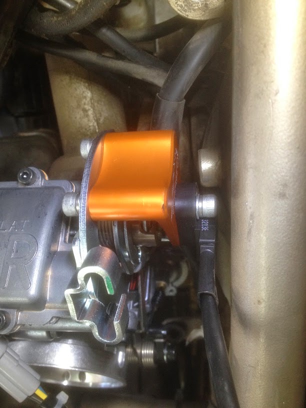
Chris at Cosentino Engineering has been making a TPS mounting kit to suit the Keihin FCR carbs when fitted to the KTMs he plays with, which have a TPS fitted as std I believe. See here for all his bits: Cosentino Engineering
I had Chris send me a kit to see how it would fit to the FCR in the SS and Monsters. The Ducati FCR fitment is a "racked" pair of carbs, as opposed to the two single carbs the KTM has. But the TPS fit is much the same. Although I believe Chris is having some brackets anodised red instead of the usual orange to appease those who like that sort of thing.
The TPS itself is a KTM part and very affordable in the grand scheme of things. And while I don't have a source for the 3 pin rounded triangular style connector on the end of it (haven't bothered to look, frankly), I do have a very functional set of wire cutters.
One change required to the Ducati FCR set is the accelerator pump arm. The original flat arm will foul the little nipple that fixes to the end of the throttle shaft, not allowing the throttle to fully close. Replacing it with a round wire arm (a GSXR part from the FCR diagrams) fixes this issue, and it's not very expensive. You can see the round wire arm in the following photos.
Some may be wondering why you would want to fit a TPS, and the answer is in combination with a 3D programmable ignition system, like the Ignitech, you can have a spark map with the benefits to fuel economy and response that this gives. Liam at Fast Bike Gear in New Zealand has written a great expanded Ignitech user guide which includes info on doing this.
Fitted to Minnie the Monster it looks like below. Plenty of clearance to the frame and everything else. The photos are a bit fuzzy, so I apologise for that. Maybe my lens is dirty.
Fitted to the 400SS, you can see the boss on the inside of the frame that holds the upper fairing mount on a half faired bike. The mount bracket goes out to the rear, so away from the TPS, but it may need trimming and a shallow head screw. I was too lazy to try refitting mine to actually check. The wiring you can see hanging usually runs above the boss, and it was definitely in the way. This bike is a '93 model, with the battery reversed as compared to the later models, so that may impact how annoying this cable actually is.
.
Chris at Cosentino Engineering has been making a TPS mounting kit to suit the Keihin FCR carbs when fitted to the KTMs he plays with, which have a TPS fitted as std I believe. See here for all his bits: Cosentino Engineering
I had Chris send me a kit to see how it would fit to the FCR in the SS and Monsters. The Ducati FCR fitment is a "racked" pair of carbs, as opposed to the two single carbs the KTM has. But the TPS fit is much the same. Although I believe Chris is having some brackets anodised red instead of the usual orange to appease those who like that sort of thing.
The TPS itself is a KTM part and very affordable in the grand scheme of things. And while I don't have a source for the 3 pin rounded triangular style connector on the end of it (haven't bothered to look, frankly), I do have a very functional set of wire cutters.
One change required to the Ducati FCR set is the accelerator pump arm. The original flat arm will foul the little nipple that fixes to the end of the throttle shaft, not allowing the throttle to fully close. Replacing it with a round wire arm (a GSXR part from the FCR diagrams) fixes this issue, and it's not very expensive. You can see the round wire arm in the following photos.
Some may be wondering why you would want to fit a TPS, and the answer is in combination with a 3D programmable ignition system, like the Ignitech, you can have a spark map with the benefits to fuel economy and response that this gives. Liam at Fast Bike Gear in New Zealand has written a great expanded Ignitech user guide which includes info on doing this.
Fitted to the 400SS, you can see the boss on the inside of the frame that holds the upper fairing mount on a half faired bike. The mount bracket goes out to the rear, so away from the TPS, but it may need trimming and a shallow head screw. I was too lazy to try refitting mine to actually check. The wiring you can see hanging usually runs above the boss, and it was definitely in the way. This bike is a '93 model, with the battery reversed as compared to the later models, so that may impact how annoying this cable actually is.
Tuesday, May 27, 2014
Marzocchi 40mm fork design and impact of oil level on spring rate, Part 3: The crap ones
.
It's amazing how a company with such a high end reputation for quality suspension, in many fields, can produce something as crap as these forks. But, as those in business will understand, if someone asks you to make something, why not. And clearly, when Ducati asked Marzocchi to make some upside down forks for the Monster and SS range in 1994, the word most emphasised was cheap. Ie, "Yes, well, they're great, but do you have anything cheaper?"
So what we got were these 40mm forks with a damper cartridge arrangement that is fixed into the fork tubes by the bottom edge of the tube being rolled to fix them. I've often poked quite a bit of fun at them, but it's not really Marzocchi's fault if it's what Ducati wanted. As always, it's amazing the crap Ducati have managed to get away with over the years.
Functionally, the forks have normal style rebound damping, but compression damping in the final 1/3 (or so) of travel only. This leads to quite a bit of initial dive, the sort of thing that catches you out when you grab a handful of front brake at low speed while working through traffic for example.
They were fitted to the Monster (M400, 600 and 750) and SS ranges (400, 600, 750 and 900SS CR) from 1995 until 1999. I have record of two different dimension springs being fitted, but the overall rate calculates at much the same. Being way too soft, and two stage to try to overcome it.
My set of these came from Minnie originally, before I fitted some 41 mm Showa non adjustable forks to her. I did replace the springs at one point, but they've been unused for quite some years now.
I had a little time and curiosity, given my other fork playing, so decided to drag them out and have a looksee.
As I found them, they were fitted with 0.85 kg/mm rate springs fitted with 33 mm of preload and filled with oil to 100 mm. Why they had 33 mm of preload I don't know, but it seems way too much. So I tested them again with 17 mm of preload and the oil level set to 140 mm. The preload tubes in this instance were pieces of 32 mm OD orange electrical conduit. This is much the same size as the original tube, in both OD and thickness. With a wall thickness of 3 mm, it does have a noticeable impact on oil level, especially when compared to the Showa thin wall steel tube preload spacers for example.
Then I dug up some original M600 springs from my stash of oldies. I couldn't find any original preload tubes (long since cut up no doubt), so I cut a piece of orange conduit 120 mm long, which I'm pretty sure is the original length. This gives 13 mm of preload on the original spring. The std oil level is 90 mm, so I began with that, then added more preload (another 20 mm piece of orange goodness), then dropped the oil level to 130 mm with the same extra preload. The orange conduit volume also had an impact here. I calculated that the 20 mm long piece of conduit added the equivalent of 5 mm of oil height to the fork internal volume. Which I'm mentioning as I didn't think of it when originally adding it, but later went "ah" when it appeared the air spring rate may have changed a touch. As ever, it's all the errors you introduce without thinking that catch you out.
And so to a graph. Blue is how I found it: 0.85 kg/mm spring with 35 mm of preload and oil set to 100 mm. Black is with the preload reduced to 17 mm and oil dropped to 140 mm. Red is with the original spring, preload and 90 mm oil level. Green is with preload increased 20 mm and 90 mm oil level. Orange is the same as the green, but with the oil level dropped 40 mm to 130 mm.
The orange and black curves show much more linearity, which is what I'm seeing a lot more of with oil levels reduced by 40 or so mm. The shape of the yellow curve is also influenced by the spring rate, which changes from soft to harder at around 70 mm of compression. With the preload set to 33 mm, this corresponds to 40 mm of fork compression, or just a bit more than the static sag would hopefully be. I have found that the static sag load seems to be in the 45 kg range, conveniently occurring around 35-ish mm of compression for the black, green and yellow curves.
If I add the M900ie 'final' curve, with the 0.85 kg/mm springs running 5 mm of adjuster added preload and oil level set to 155 mm in purple, the orange and black look a bit light on at the top end. Given the black and purple springs are both allegedly 0.85 kg/mm the difference in overall gradient is a bit odd. I'd probably want to go back up in oil height by maybe 20 mm or so to increase the air spring.
Splitting them up for clarity, first a 20 mm increase in preload with the original spring. The difference in static sag with this change should be in the region of 15 mm.
Then a 40 mm drop in oil level. It's only in the last 1/3 of the travel that you'd notice any difference on the road.
The difference a heavier spring makes to the mid travel range is shown in the next graph. Similar end points, but a difference in the middle of around 8 mm for a given load. Black is 0.85 kg/mm, orange original.
It's amazing how a company with such a high end reputation for quality suspension, in many fields, can produce something as crap as these forks. But, as those in business will understand, if someone asks you to make something, why not. And clearly, when Ducati asked Marzocchi to make some upside down forks for the Monster and SS range in 1994, the word most emphasised was cheap. Ie, "Yes, well, they're great, but do you have anything cheaper?"
So what we got were these 40mm forks with a damper cartridge arrangement that is fixed into the fork tubes by the bottom edge of the tube being rolled to fix them. I've often poked quite a bit of fun at them, but it's not really Marzocchi's fault if it's what Ducati wanted. As always, it's amazing the crap Ducati have managed to get away with over the years.
Functionally, the forks have normal style rebound damping, but compression damping in the final 1/3 (or so) of travel only. This leads to quite a bit of initial dive, the sort of thing that catches you out when you grab a handful of front brake at low speed while working through traffic for example.
They were fitted to the Monster (M400, 600 and 750) and SS ranges (400, 600, 750 and 900SS CR) from 1995 until 1999. I have record of two different dimension springs being fitted, but the overall rate calculates at much the same. Being way too soft, and two stage to try to overcome it.
My set of these came from Minnie originally, before I fitted some 41 mm Showa non adjustable forks to her. I did replace the springs at one point, but they've been unused for quite some years now.
I had a little time and curiosity, given my other fork playing, so decided to drag them out and have a looksee.
As I found them, they were fitted with 0.85 kg/mm rate springs fitted with 33 mm of preload and filled with oil to 100 mm. Why they had 33 mm of preload I don't know, but it seems way too much. So I tested them again with 17 mm of preload and the oil level set to 140 mm. The preload tubes in this instance were pieces of 32 mm OD orange electrical conduit. This is much the same size as the original tube, in both OD and thickness. With a wall thickness of 3 mm, it does have a noticeable impact on oil level, especially when compared to the Showa thin wall steel tube preload spacers for example.
Then I dug up some original M600 springs from my stash of oldies. I couldn't find any original preload tubes (long since cut up no doubt), so I cut a piece of orange conduit 120 mm long, which I'm pretty sure is the original length. This gives 13 mm of preload on the original spring. The std oil level is 90 mm, so I began with that, then added more preload (another 20 mm piece of orange goodness), then dropped the oil level to 130 mm with the same extra preload. The orange conduit volume also had an impact here. I calculated that the 20 mm long piece of conduit added the equivalent of 5 mm of oil height to the fork internal volume. Which I'm mentioning as I didn't think of it when originally adding it, but later went "ah" when it appeared the air spring rate may have changed a touch. As ever, it's all the errors you introduce without thinking that catch you out.
And so to a graph. Blue is how I found it: 0.85 kg/mm spring with 35 mm of preload and oil set to 100 mm. Black is with the preload reduced to 17 mm and oil dropped to 140 mm. Red is with the original spring, preload and 90 mm oil level. Green is with preload increased 20 mm and 90 mm oil level. Orange is the same as the green, but with the oil level dropped 40 mm to 130 mm.
The orange and black curves show much more linearity, which is what I'm seeing a lot more of with oil levels reduced by 40 or so mm. The shape of the yellow curve is also influenced by the spring rate, which changes from soft to harder at around 70 mm of compression. With the preload set to 33 mm, this corresponds to 40 mm of fork compression, or just a bit more than the static sag would hopefully be. I have found that the static sag load seems to be in the 45 kg range, conveniently occurring around 35-ish mm of compression for the black, green and yellow curves.
If I add the M900ie 'final' curve, with the 0.85 kg/mm springs running 5 mm of adjuster added preload and oil level set to 155 mm in purple, the orange and black look a bit light on at the top end. Given the black and purple springs are both allegedly 0.85 kg/mm the difference in overall gradient is a bit odd. I'd probably want to go back up in oil height by maybe 20 mm or so to increase the air spring.
Splitting them up for clarity, first a 20 mm increase in preload with the original spring. The difference in static sag with this change should be in the region of 15 mm.
Then a 40 mm drop in oil level. It's only in the last 1/3 of the travel that you'd notice any difference on the road.
The difference a heavier spring makes to the mid travel range is shown in the next graph. Similar end points, but a difference in the middle of around 8 mm for a given load. Black is 0.85 kg/mm, orange original.
Thursday, May 22, 2014
Ducati Gold Coast special clearance sale
.
No affiliation, but Ducati Gold Coast are running a special clearance sale. some of it is old DP accessories, including some Termi stuff that is now long gone for Monster and SS for instance. Have a looksee here:
Ducati Gold Coast sale
.
No affiliation, but Ducati Gold Coast are running a special clearance sale. some of it is old DP accessories, including some Termi stuff that is now long gone for Monster and SS for instance. Have a looksee here:
Ducati Gold Coast sale
.
Wednesday, May 21, 2014
Showa 43mm adjustable fork design and impact of oil level on spring rate, Part 2: 748 / 916 / 996 / etc
.
Today while I was doing a major service on a 748 I took the opportunity to throw a fork in the rig and see how it compared to the others. I really wasn't sure what to expect, but was surprised anyway. It's always nice to be surprised.
While the 748 forks (same as 916 and 996) are also 43 mm Showa adjustable, they differ internally to the M900ie forks by having the long rebound adjuster rod as discussed long ago in the 1000SS fork post. All 916 on SBK have this style fork (except 749 Dark). Assembly wise, there is a 100 mm long thin wall steel tube spacer and spring supporting washer below the spring and the usual Showa style preload tube above the spring. I set the oil level with the lower spacer and washer fitted, as the manual doesn't specifically say to not fit them. I'm not sure if that's right or not, but it's not mentioned and will result in a lower final oil level and I'm liking that these days.
The 748 forks have an oil spec of 132 mm. I suspect this one was more like 142 mm before I pull them apart. I couldn't get an accurate measure as the bottom plastic bush on the preload tube came off in the forks, making it pretty much impossible to get the spring out without tipping them upside down and shaking. But the level with spring and bottom plastic bush in was about 10 mm lower before compared to after when set to 132 mm.
The spring in the 748 is a linear spring 285 mm long and the rate calculated at 1.00 kg/mm. I didn't have time to measure it, but the calculation is generally very accurate. So while it's a bit heavier than the others, it's fitted with only 8 mm of preload with the adjusters at the minimum setting. Like the M900ie fork, the adjuster range is 15 mm.
To the curves: red is 748 with minimum preload, blue 748 with maximum preload, yellow M900ie as was originally with maximum preload and green is how I set the M900ie fork up at the end. I don't feel so bad about my M900ie setting now. Again, the coincidence of unrelated results is quite amazing.
Also again, it amazes me that you can hit (so near to) the same target with such variation in spring rate. Although the rate variation in this case is a little less than the variation in the M400ie leg. And the unknown is the variance in internal fork volume once assembled, as the different springs and spacers all contribute sometimes vastly different volumes.
This graph shows the collection of springs as encountered in these reports so far. For this report, purple and green are the contributors.
One point that just occurred to me is that of fork swaps. Often you'll read forum threads of where someone has fitted SBK forks to their Monster or other and the poster will be told of how the spring rates will be wrong. I might even have said it myself. But the above comparison of the 748 "as delivered" curve and what I decided was a good curve for a M900ie shows once again that, unless you actually check something, you really don't know whether you're talking through your arse or not.
Of course, all of this is separate to damping rates and their influence. I'm not getting into damping rates at all. That's completely out of my realm of experience, and it's an area where specialist experience is what matters.
.
Today while I was doing a major service on a 748 I took the opportunity to throw a fork in the rig and see how it compared to the others. I really wasn't sure what to expect, but was surprised anyway. It's always nice to be surprised.
While the 748 forks (same as 916 and 996) are also 43 mm Showa adjustable, they differ internally to the M900ie forks by having the long rebound adjuster rod as discussed long ago in the 1000SS fork post. All 916 on SBK have this style fork (except 749 Dark). Assembly wise, there is a 100 mm long thin wall steel tube spacer and spring supporting washer below the spring and the usual Showa style preload tube above the spring. I set the oil level with the lower spacer and washer fitted, as the manual doesn't specifically say to not fit them. I'm not sure if that's right or not, but it's not mentioned and will result in a lower final oil level and I'm liking that these days.
The 748 forks have an oil spec of 132 mm. I suspect this one was more like 142 mm before I pull them apart. I couldn't get an accurate measure as the bottom plastic bush on the preload tube came off in the forks, making it pretty much impossible to get the spring out without tipping them upside down and shaking. But the level with spring and bottom plastic bush in was about 10 mm lower before compared to after when set to 132 mm.
The spring in the 748 is a linear spring 285 mm long and the rate calculated at 1.00 kg/mm. I didn't have time to measure it, but the calculation is generally very accurate. So while it's a bit heavier than the others, it's fitted with only 8 mm of preload with the adjusters at the minimum setting. Like the M900ie fork, the adjuster range is 15 mm.
To the curves: red is 748 with minimum preload, blue 748 with maximum preload, yellow M900ie as was originally with maximum preload and green is how I set the M900ie fork up at the end. I don't feel so bad about my M900ie setting now. Again, the coincidence of unrelated results is quite amazing.
Also again, it amazes me that you can hit (so near to) the same target with such variation in spring rate. Although the rate variation in this case is a little less than the variation in the M400ie leg. And the unknown is the variance in internal fork volume once assembled, as the different springs and spacers all contribute sometimes vastly different volumes.
This graph shows the collection of springs as encountered in these reports so far. For this report, purple and green are the contributors.
One point that just occurred to me is that of fork swaps. Often you'll read forum threads of where someone has fitted SBK forks to their Monster or other and the poster will be told of how the spring rates will be wrong. I might even have said it myself. But the above comparison of the 748 "as delivered" curve and what I decided was a good curve for a M900ie shows once again that, unless you actually check something, you really don't know whether you're talking through your arse or not.
Of course, all of this is separate to damping rates and their influence. I'm not getting into damping rates at all. That's completely out of my realm of experience, and it's an area where specialist experience is what matters.
.
Friday, May 16, 2014
Showa 43mm adjustable fork design and impact of oil level on spring rate, Part 1: M900ie
.
Or, keeping the same title so as to be consistent with the previous playing with forks.
So I got to play with a set of 43 mm Showa adjustable forks from a 2000 M900Sie today. Well, I'm halfway through it. I have serviced the forks in this bike once previously, and filled them with 5 weight oil to the spec height of 108 mm.
I thought to start with I'd do the same travel vs load graph (mm across the bottom, kg up the side) as for the Marzocchi forks, and then thought I'd add the original curve for the 43 mm Marzocchi with oil set to the spec height (105 mm?). Turned out to be a bit spooky, frankly.
Red is the Showa with preload at maximum, yellow Showa with preload at minimum and blue Marzocchi. Not really what I was expecting, and a wee bit eerie. Obviously someone at Ducati thinks this is an ideal fork setting. The difference between minimum and maximum preload is 15 mm, with this translating to 19 and 34 mm of total preload in the assembled forks.
More to come. It's going to get some 0.85 kg/mm springs (rider 80 kg) and I'll drop the oil to 140 or so mm.
Ok, so on to the more.
I was very surprised by the fact that the air spring effect in the Showa was pretty much identical to the Marzocchi. Looking at the parts, the Showa has a longer spring (349 mm) that sits at the bottom of the fork around the cartridge, with a long, but thin steel preload tube (277 mm) above it. The Marzocchi has a shorter spring (249 mm) that sits on top of a stepped washer that itself sits on top of the cartridge, with a thick wall plastic preload tube (38 mm OD, 30 mm ID, about 100 mm long) sitting above (or maybe below, now that I think about it) the spring. So perhaps it's just the visual weight of the shorter, but thicker Marzocchi preload tube that gives the impression. Anyway, it was certainly not what I expected.
I replaced the original springs with a shorter, mostly linear rate spring (with a couple of tight coils at one end) which are meant to be 0.85 kg/mm. I tested them on my amateur rig and came up with the curve below. At 50 mm compression they average 0.85 kg/mm, but by 100 mm compression they're up to 0.90 kg/mm. The OEM and ST series springs from the previous Marzocchi report are also included. The two OEM springs are pretty close overall. The Showa spring curve starts a bit higher, as it was a touch too long for how I had my rig set up, and also after midnight. Dimension wise, the Showa spring has less coils (harder), but thinner wire (softer) and they're both 38.6 mm OD.
I fitted the 0.85 springs with 10 mm of preload (adjuster at minimum). These springs are 282 mm long, requiring longer 335 mm preload tubes. This is usual when replacing fork springs. The only springs I know of that come at the same length as the originals are Ohlins, where they generally have a uniform length for a given application. For the preload tubes I use 32mm aluminium tube with a 1.6 mm wall. Unfortunately, the original steel tubes have a slightly larger ID, which means, when using this aluminium tube, I have to machine down the plastic end pieces Showa use to allow them to slide inside the aluminium. The chuck ID on my little lathe is just a touch too small to allow the tubes to slide inside and be held at the machining end, so it's much less destructive to do the plastic pieces.
I set the oil level to 140 mm, thinking this would be a good starting point. I did check the difference in oil quantity between 120 and 140 mm, so I could make changes based on quantity once the forks were all together. This saves having to strip them all apart again. At 120 mm oil height, the fork had 475 ml of oil in them. Dropping the level to 140 took out 27 ml. So if I wanted to go back to 120 mm I would just add 27 ml. Or, conversely, if I wanted to go down to 160 mm, I could just suck out another 27 ml.
So, to the curve for 0.85 kg/mm springs with 140 mm oil height. Not exactly what I was hoping for comparatively. Red is OEM with max preload, yellow is OEM with minimum preload, blue 0.85 with max preload, green 0.85 with minimum preload.
I had figured that the 0.85 kg/mm springs would need about 5 mm of preload to give the right sag, which would place them about 1/3 of the way between the green and blue lines. But the overall result is still a rather high rate of increase in effective spring rate near full compression. Adding two further curves from the Marzocchi fork report, being the OEM spring with preload increased by 15 mm in orange and oil set to 145 mm and the ST series spring with oil set to 145 mm in purple, shows what I ended up with there.
So we come back to the question of how much load will the forks see? Peter at Promecha told me that the maximum load (non impact if you like) the forks will see is if the bike is standing on its nose under hard braking with the rear wheel in the air. And also that you don't spring them that hard, as it doesn't really work that way. Which makes sense now that I've seen the impact of the air spring.
If we assume this M900Sie weighs 200 kg ready to go, and with the rider weighing 80 kg, plus 5 kg for gear, and taking off 5 kg to allow for the unsprung weight of the front wheel and fork lowers, that's 280 kg or 140 kg per leg. These forks have around 115 mm of travel. If we sprung it assuming the springs themselves supported all the load, 140 kg at 115 mm of travel gives a rate of 1.22 kg/mm. But once we introduce the air spring effect, the required spring rate drops quite a lot. With the 0.85 kg/mm springs, 145 mm oil level and my planned 5 mm of preload, that load will only give around 100 mm of compression.
How the bike was set up when it arrived, with the preload set to maximum on the OEM springs (the red curve), the same load would have given 95 mm of compression.
So it looks like I need to lose some more oil. I'm quite disappointed with how this is turning out. Not at all as I had expected.
Back again after losing some oil. I sucked out 40 ml of oil, which should relate to 30 mm. The change is somewhat as expected, as below: purple 140 mm, red 170 mm. Both curves with minimum preload.
With my intention of running more preload, I made another calculated curve based on adding 5 mm of preload (1/3 of the maximum) and raising the oil level to 155 mm, 1/2 way between the two tested levels above. The result wouldn't be exactly 1/2, as the change in air spring rate is slightly exponential. I gave it 60% as a (random) guess, and came up with the curve below. It's the yellow one.
I haven't ridden this one as yet, but given the chances of me exploring the end limits on a customer's bike during a suburban road test are non existent, I'll have to wait and see how the owner finds it. The graph below shows how it arrived in red and how it is now in yellow. There's not a lot of difference to show for my several hours of messing around, but the change in the last 1/3 of travel is what this has all been about anyway. I would hope it's much more compliant, and less likely to make the big bumps feel big. If that's not a poor way to describe it.
I got to thinking today that I had seen a fork oil level spec somewhere that always seemed pretty odd. Turns out it was the 888. The 888 has 41 mm Showa adjustable forks, much the same internally as the 43 mm forks fitted to this Monster. The carburetor model 900SS used the same forks as the 888, albeit with the soft crappy dual rate springs in place of what I recall are much firmer, linear rate springs in the 888. The oil level specified for the 888 is 162 mm and for the SS it's 108 mm, the same as this Monster. I wonder why there was so much difference?
The 916 oil level is 135 mm, and the manual says "Oil quantity affects fork behaviour at full compression. Compression load increases or decreases with oil level." It also gives a minimum level of 150 mm and a maximum of 106 mm.
Which brings us to the end for now pretty much. I'm curious to try some of the other forks I have kicking around, being the 40 mm Marzocchi and the 41 mm Showa non adjustable forks fitted to 90's Monsters. Both of these had quite high oil levels specified, 90 mm for the Marzocchi and 80 mm for the Showa.
Plus there was a service bulletin for the M900 with the 41 mm Showa that recommended adding 30 ml of oil on top of the 80 mm spec. This was aimed at helping the fork performance at full compression. I'm curious to run them on my test rig to see how they behave, as it just seems like way too much oil.
More rambling to come. Lucky you lot eh.
.
Or, keeping the same title so as to be consistent with the previous playing with forks.
So I got to play with a set of 43 mm Showa adjustable forks from a 2000 M900Sie today. Well, I'm halfway through it. I have serviced the forks in this bike once previously, and filled them with 5 weight oil to the spec height of 108 mm.
I thought to start with I'd do the same travel vs load graph (mm across the bottom, kg up the side) as for the Marzocchi forks, and then thought I'd add the original curve for the 43 mm Marzocchi with oil set to the spec height (105 mm?). Turned out to be a bit spooky, frankly.
Red is the Showa with preload at maximum, yellow Showa with preload at minimum and blue Marzocchi. Not really what I was expecting, and a wee bit eerie. Obviously someone at Ducati thinks this is an ideal fork setting. The difference between minimum and maximum preload is 15 mm, with this translating to 19 and 34 mm of total preload in the assembled forks.
More to come. It's going to get some 0.85 kg/mm springs (rider 80 kg) and I'll drop the oil to 140 or so mm.
Ok, so on to the more.
I was very surprised by the fact that the air spring effect in the Showa was pretty much identical to the Marzocchi. Looking at the parts, the Showa has a longer spring (349 mm) that sits at the bottom of the fork around the cartridge, with a long, but thin steel preload tube (277 mm) above it. The Marzocchi has a shorter spring (249 mm) that sits on top of a stepped washer that itself sits on top of the cartridge, with a thick wall plastic preload tube (38 mm OD, 30 mm ID, about 100 mm long) sitting above (or maybe below, now that I think about it) the spring. So perhaps it's just the visual weight of the shorter, but thicker Marzocchi preload tube that gives the impression. Anyway, it was certainly not what I expected.
I replaced the original springs with a shorter, mostly linear rate spring (with a couple of tight coils at one end) which are meant to be 0.85 kg/mm. I tested them on my amateur rig and came up with the curve below. At 50 mm compression they average 0.85 kg/mm, but by 100 mm compression they're up to 0.90 kg/mm. The OEM and ST series springs from the previous Marzocchi report are also included. The two OEM springs are pretty close overall. The Showa spring curve starts a bit higher, as it was a touch too long for how I had my rig set up, and also after midnight. Dimension wise, the Showa spring has less coils (harder), but thinner wire (softer) and they're both 38.6 mm OD.
I fitted the 0.85 springs with 10 mm of preload (adjuster at minimum). These springs are 282 mm long, requiring longer 335 mm preload tubes. This is usual when replacing fork springs. The only springs I know of that come at the same length as the originals are Ohlins, where they generally have a uniform length for a given application. For the preload tubes I use 32mm aluminium tube with a 1.6 mm wall. Unfortunately, the original steel tubes have a slightly larger ID, which means, when using this aluminium tube, I have to machine down the plastic end pieces Showa use to allow them to slide inside the aluminium. The chuck ID on my little lathe is just a touch too small to allow the tubes to slide inside and be held at the machining end, so it's much less destructive to do the plastic pieces.
I set the oil level to 140 mm, thinking this would be a good starting point. I did check the difference in oil quantity between 120 and 140 mm, so I could make changes based on quantity once the forks were all together. This saves having to strip them all apart again. At 120 mm oil height, the fork had 475 ml of oil in them. Dropping the level to 140 took out 27 ml. So if I wanted to go back to 120 mm I would just add 27 ml. Or, conversely, if I wanted to go down to 160 mm, I could just suck out another 27 ml.
So, to the curve for 0.85 kg/mm springs with 140 mm oil height. Not exactly what I was hoping for comparatively. Red is OEM with max preload, yellow is OEM with minimum preload, blue 0.85 with max preload, green 0.85 with minimum preload.
I had figured that the 0.85 kg/mm springs would need about 5 mm of preload to give the right sag, which would place them about 1/3 of the way between the green and blue lines. But the overall result is still a rather high rate of increase in effective spring rate near full compression. Adding two further curves from the Marzocchi fork report, being the OEM spring with preload increased by 15 mm in orange and oil set to 145 mm and the ST series spring with oil set to 145 mm in purple, shows what I ended up with there.
So we come back to the question of how much load will the forks see? Peter at Promecha told me that the maximum load (non impact if you like) the forks will see is if the bike is standing on its nose under hard braking with the rear wheel in the air. And also that you don't spring them that hard, as it doesn't really work that way. Which makes sense now that I've seen the impact of the air spring.
If we assume this M900Sie weighs 200 kg ready to go, and with the rider weighing 80 kg, plus 5 kg for gear, and taking off 5 kg to allow for the unsprung weight of the front wheel and fork lowers, that's 280 kg or 140 kg per leg. These forks have around 115 mm of travel. If we sprung it assuming the springs themselves supported all the load, 140 kg at 115 mm of travel gives a rate of 1.22 kg/mm. But once we introduce the air spring effect, the required spring rate drops quite a lot. With the 0.85 kg/mm springs, 145 mm oil level and my planned 5 mm of preload, that load will only give around 100 mm of compression.
How the bike was set up when it arrived, with the preload set to maximum on the OEM springs (the red curve), the same load would have given 95 mm of compression.
So it looks like I need to lose some more oil. I'm quite disappointed with how this is turning out. Not at all as I had expected.
Back again after losing some oil. I sucked out 40 ml of oil, which should relate to 30 mm. The change is somewhat as expected, as below: purple 140 mm, red 170 mm. Both curves with minimum preload.
With my intention of running more preload, I made another calculated curve based on adding 5 mm of preload (1/3 of the maximum) and raising the oil level to 155 mm, 1/2 way between the two tested levels above. The result wouldn't be exactly 1/2, as the change in air spring rate is slightly exponential. I gave it 60% as a (random) guess, and came up with the curve below. It's the yellow one.
I got to thinking today that I had seen a fork oil level spec somewhere that always seemed pretty odd. Turns out it was the 888. The 888 has 41 mm Showa adjustable forks, much the same internally as the 43 mm forks fitted to this Monster. The carburetor model 900SS used the same forks as the 888, albeit with the soft crappy dual rate springs in place of what I recall are much firmer, linear rate springs in the 888. The oil level specified for the 888 is 162 mm and for the SS it's 108 mm, the same as this Monster. I wonder why there was so much difference?
The 916 oil level is 135 mm, and the manual says "Oil quantity affects fork behaviour at full compression. Compression load increases or decreases with oil level." It also gives a minimum level of 150 mm and a maximum of 106 mm.
Which brings us to the end for now pretty much. I'm curious to try some of the other forks I have kicking around, being the 40 mm Marzocchi and the 41 mm Showa non adjustable forks fitted to 90's Monsters. Both of these had quite high oil levels specified, 90 mm for the Marzocchi and 80 mm for the Showa.
Plus there was a service bulletin for the M900 with the 41 mm Showa that recommended adding 30 ml of oil on top of the 80 mm spec. This was aimed at helping the fork performance at full compression. I'm curious to run them on my test rig to see how they behave, as it just seems like way too much oil.
More rambling to come. Lucky you lot eh.
.
Tuesday, May 6, 2014
Marzocchi 43mm fork design and impact of oil level on spring rate, Part 3: More fork details
.
Just a short update. I had an S2R800 in today for service and had the forks apart. While they looked identical to the Marzocchi ones, I noticed that the markings in the inside of the lowers were different. On closer comparison, it's the brand part that is different, everything else is identical. I have no idea who makes them, but it is a symbol I see on a lot of these late model forks. Photos below show them, Marzocchi with 'M' cast logo on left.
I did notice that the RH leg, which is the one I had played with previously, had rebound damping and no compression. But the LH leg had compression damping and no rebound. A little for most of the travel, a lot more in the last 30mm or so. So as a combination they provide both, and that way you can tailor them as desired individually with different oil weights for example.
I added 15mm more preload, using pieces cut from an original spacer. I'm not sure 15mm is enough now that I think about it, given it had nearly 55mm of sag before we started. But we'll see. I also dropped the oil level to 135mm.
.
Just a short update. I had an S2R800 in today for service and had the forks apart. While they looked identical to the Marzocchi ones, I noticed that the markings in the inside of the lowers were different. On closer comparison, it's the brand part that is different, everything else is identical. I have no idea who makes them, but it is a symbol I see on a lot of these late model forks. Photos below show them, Marzocchi with 'M' cast logo on left.
I did notice that the RH leg, which is the one I had played with previously, had rebound damping and no compression. But the LH leg had compression damping and no rebound. A little for most of the travel, a lot more in the last 30mm or so. So as a combination they provide both, and that way you can tailor them as desired individually with different oil weights for example.
I added 15mm more preload, using pieces cut from an original spacer. I'm not sure 15mm is enough now that I think about it, given it had nearly 55mm of sag before we started. But we'll see. I also dropped the oil level to 135mm.
.
Thursday, April 24, 2014
Friday, April 18, 2014
Lift graph for 4V Desmoquattro cams using strada inlet cam as exhaust cam
I thought I'd post a graph here for a conversation that I've been having with someone about using the 4V Desmoquattro strada inlet cam as an exhaust cam. I haven't tried this personally, but have been told it works well.
In the graph, you can see the exhaust cams on the LH side. The yellow curve is the G, the corse exhaust cam used from 1992 (888 SPS had it too) until the last of them in 2000. They obviously liked it. The 916/999SPS exhaust cam (blue), while having much less duration, has a fairly similar shape and compared to the pink strada exhaust curve, is completely different. The strada is much slower opening, with what is called an asymmetric profile. The point of this graph, the red line, is the strada inlet cam being used as an exhaust. Profile wise it is very similar to the SPS up to peak lift, although it doesn't hold the peak or closing profile as long. But much better than the strada exhaust, and the SPS cam set does work very well. It's not a straight fit, the closing lobe needs to be narrowed and the opening rockers need some grinding at the feet. But well worth the effort given the cost and complete unavailability of the SPS cams.
How much input the SPS inlet has over the strada inlet in comparison I don't know. The extra high lift duration of the SPS inlet is something the specs don't show on their own, and that sort of extra area under the graph can only be good. The orange curve is the 748RS '506' cam, shown because there's some on Ebay at the moment and duration wise they only have 5 degrees more than the SPS and 11 degrees more than the strada. They do have a lot more lift, and are quite aggressive acceleration wise. But if you kept them to around 10,000 rpm, not the 13,000 or so they would have seen trying rather vainly to keep the Japanese 600's in sight, they won't be too destructive I'd think.
Doug Lofgren's cam page has more info on them too, with cam doctor graphs.
In the graph, you can see the exhaust cams on the LH side. The yellow curve is the G, the corse exhaust cam used from 1992 (888 SPS had it too) until the last of them in 2000. They obviously liked it. The 916/999SPS exhaust cam (blue), while having much less duration, has a fairly similar shape and compared to the pink strada exhaust curve, is completely different. The strada is much slower opening, with what is called an asymmetric profile. The point of this graph, the red line, is the strada inlet cam being used as an exhaust. Profile wise it is very similar to the SPS up to peak lift, although it doesn't hold the peak or closing profile as long. But much better than the strada exhaust, and the SPS cam set does work very well. It's not a straight fit, the closing lobe needs to be narrowed and the opening rockers need some grinding at the feet. But well worth the effort given the cost and complete unavailability of the SPS cams.
How much input the SPS inlet has over the strada inlet in comparison I don't know. The extra high lift duration of the SPS inlet is something the specs don't show on their own, and that sort of extra area under the graph can only be good. The orange curve is the 748RS '506' cam, shown because there's some on Ebay at the moment and duration wise they only have 5 degrees more than the SPS and 11 degrees more than the strada. They do have a lot more lift, and are quite aggressive acceleration wise. But if you kept them to around 10,000 rpm, not the 13,000 or so they would have seen trying rather vainly to keep the Japanese 600's in sight, they won't be too destructive I'd think.
Doug Lofgren's cam page has more info on them too, with cam doctor graphs.
Saturday, April 12, 2014
Timing belt pulley positioning on belt drive Ducatis
There's a thread going on one of the forums about replacing belts, and the point of marking the belts has been raised. I made the comment that I found the marking of belts an over complication of the procedure, but some people do find some comfort in it. In particular for locating the vertical camshaft correctly (vertical inlet on a 4V), due to the load the vertical inlet closing spring places on the camshaft when the cam is at the correct position. Coupled to the fact that on most of the 2V models the vertical cam pulley has a surround covering it and making it hard to get a good hold of it. I can understand the issues this brings to those who do this very infrequently.
So, to confuse people further, I thought I'd introduce another method to bypass this. I did teach this method to a previous workmate, who them went and bent some valves, so if you don't understand it, don't use it. But it seems pretty simple to me.
The timing shaft pullies traditionally have 4 holes in them, and the locating dot on the outer edge. See the picture below:
In this instance, the locating dot is lined up with the mark on the primary drive cover. This denotes the engine is at TDC firing on the horizontal cylinder, which is the master position for most setting procedures.
As the timing shaft turns at half crank speed, it rotates 180 degrees for one crankshaft rotation. From the RH side the crankshaft rotates clockwise and the timing shaft rotates counter clockwise. Vertical TDC firing is 270 crankshaft degrees after horizontal TDC firing, or 135 timing shaft degrees. If you look at the above, you can see 4 holes spaced at 90 degrees, and conveniently located at 45 degree spacing either side of the locating dot. This means that the second hole clockwise from the locating dot is 135 timing degrees from horizontal TDC firing, and as such, it's a locating dot for vertical TDC firing when aligned with any of the aligning marks on the primary drive cover or camshaft surrounds. As below:
On the engines with adjustable cam pullies, these holes aren't present. But of the three locking screws that hold the halves together, one is in the correct position.
The locating dot still gives the position anyway. On the 2V pre DS motors, when the timing shaft dot is at 3 o'clock, the vertical camshaft dot will be at 4:30.
On the later 4V Testastretta and 2V DS style engines with the 20 tooth pullies, the small holes are still there. But there are many larger holes, just to confuse the issue.
And, as always, when done, the locating dots on the timing shaft and all cam pullies must align with all the correct marks once set back to horizontal TDC firing.
So, to confuse people further, I thought I'd introduce another method to bypass this. I did teach this method to a previous workmate, who them went and bent some valves, so if you don't understand it, don't use it. But it seems pretty simple to me.
The timing shaft pullies traditionally have 4 holes in them, and the locating dot on the outer edge. See the picture below:
In this instance, the locating dot is lined up with the mark on the primary drive cover. This denotes the engine is at TDC firing on the horizontal cylinder, which is the master position for most setting procedures.
As the timing shaft turns at half crank speed, it rotates 180 degrees for one crankshaft rotation. From the RH side the crankshaft rotates clockwise and the timing shaft rotates counter clockwise. Vertical TDC firing is 270 crankshaft degrees after horizontal TDC firing, or 135 timing shaft degrees. If you look at the above, you can see 4 holes spaced at 90 degrees, and conveniently located at 45 degree spacing either side of the locating dot. This means that the second hole clockwise from the locating dot is 135 timing degrees from horizontal TDC firing, and as such, it's a locating dot for vertical TDC firing when aligned with any of the aligning marks on the primary drive cover or camshaft surrounds. As below:
On the engines with adjustable cam pullies, these holes aren't present. But of the three locking screws that hold the halves together, one is in the correct position.
The locating dot still gives the position anyway. On the 2V pre DS motors, when the timing shaft dot is at 3 o'clock, the vertical camshaft dot will be at 4:30.
On the later 4V Testastretta and 2V DS style engines with the 20 tooth pullies, the small holes are still there. But there are many larger holes, just to confuse the issue.
And, as always, when done, the locating dots on the timing shaft and all cam pullies must align with all the correct marks once set back to horizontal TDC firing.
Sunday, April 6, 2014
Fitting a 2003 onwards 696/796/800 6 speed gearbox into a pre 1998 600/750
One of the motors I have in bits is a 600SS motor, which came from the bike I sold the original engine from Minnie into. I actually sold more of this engine last week, just to make it harder for me to pointlessly waste a heap of money rebuilding it. This was mostly due to a mock up of the bits I had done the week before, trying the 68 mm stroke 900SS crank (a narrow one) to see what happened.
There was contact in a couple of places between the crank webs and the cases, at the inside of the starter drive idler gear boss in the LH case, and in a similar position on the RH, with a casting ridge that I'm guessing would be for an oil gallery. So I can't really cut either out, meaning the crank would have to be relieved at the outer edge, which reduces the most significant section of balance weight (furthest from the centreline).
The same section of crank web also hit the timing shaft on the RH side, where the later model timing shafts don't have a locating ridge. The pre 98 small blocks have a timing shaft that is shimmed between the cases to locate it, unlike the big block or 98 on small blocks where the shaft is held against the LH bearing by the timing gear.
The bottom of the 600 cylinder did just clear the web, with the underside of the piston quite a distance away. And the rods cleared the timing shaft.
And the 620 pistons I was going to use (it was going to have 750 heads, similar chamber to 620 and much larger than the small chamber in the 600 heads, which I had sold anyway) stick out a bit, but a thick base gasket shaped spacer would fix that. The 6.5 mm stroke difference between 620 and 900 (61.5 mm to 68 mm) would suggest the spacer would need to be 3.25 mm thick.
Anyway, I digress. The point of this was trying to put a late model small block 6 speed into pre 98 cases. The complete 6 speed box I bought from Ebay was from an M696. The easiest way to show why it wont drop in is with some photos.
Input shaft:
The input shaft has a larger nut on the clutch end, like all other late model boxes. So you'd need a bigger nut and possibly to do something to the clutch hub to accommodate it. The length of the clutch snout looks to be the same from threaded end to first gear. I didn't notice any difference there, but I didn't measure them. I might do that. 6 speed at the top.
The LH end of the input shaft has an extension that goes through into the recess which the clutch pushrod passes through. As the pre 98 doesn't have the clutch pushrod passing from left to right, there's no need for the extra snout, and no room in the LH case for it anyway. It has to be removed, and I figured the drop saw would take care of that.
Output shaft:
Not a great deal of difference here. The shaft outside of the LH bearing is 10 mm longer on the 6 speed, but you'd just turn the sprocket around to fix that. The only other thing I noticed is that, while both shafts are 25 mm diameter at the sprocket spline, the 6 speed wouldn't slide into my 600 cases like the 5 speed did. Maybe it just didn't want to be there.
Shift drum:
The shift drum is the biggest issue, with quite significant differences.
The RH end of the 6 speed drum has the 6 groove snout (2) for the sprung detente lever the later bikes use. You can see at the bottom left of the snout that one ridge is missing its top, that's neutral. The sprung detente lever at the RH end of the shift drum was introduced with the 916 from memory, and every new model since has adopted it. The sprung ball detente at the LH end of the shift drum is now only for neutral, so there is only one corresponding groove in the LH end.
The neutral light activation has gone from a 2 wire switch that is pushed in by the lump on the 5 speed drum (3) to a single wire switch that is earthed by the drum itself. The light brown covering on the drum, with the space at the (3), is an insulating coating that keeps the earth circuit open at all times except for when the drum is in the neutral position.
The difference in the shift fork groove pattern is obvious, so clearly you can't use a 5 speed drum.
I had various thoughts for overcoming these issues, from cutting and shutting the end of the 5 speed drum onto the 6 speed drum to making a spacer ring and welding on a switch pushing lump and cutting off the detent snout with the drop saw. Attempting the shut once the cuts were made is the only way you would be able to determine if that was a viable option. If not, you have two scrap shift drums.
So I didn't get any further with this fitment.
The other issue I have with the concept is that while a 6 speed is nice, the niceness comes from the ratio spread. The 5 speed ratio spread is 2.59, the 6 speed is 2.67. The big block wide ratio 6 speed is 2.88, a comparatively much bigger change. To overcome this there is the possibility of having another gear made for 6th, either 1 tooth bigger on the input or 1 tooth smaller on the output. The 26/24 ratio gives an 8% gap between 5th and 6th. 27/24 gives an 11% gap, 26/23 12%, with a ratio spread of 2.78. That makes about a 3 tooth on the rear difference between the top gear ratio of the 5 and 6 speeds. The shape of the current teeth determines if the 1 tooth idea will fly. The input shaft gear will be the easiest to make, as the output shaft gear has a shift fork groove on it.
.
There was contact in a couple of places between the crank webs and the cases, at the inside of the starter drive idler gear boss in the LH case, and in a similar position on the RH, with a casting ridge that I'm guessing would be for an oil gallery. So I can't really cut either out, meaning the crank would have to be relieved at the outer edge, which reduces the most significant section of balance weight (furthest from the centreline).
The same section of crank web also hit the timing shaft on the RH side, where the later model timing shafts don't have a locating ridge. The pre 98 small blocks have a timing shaft that is shimmed between the cases to locate it, unlike the big block or 98 on small blocks where the shaft is held against the LH bearing by the timing gear.
The bottom of the 600 cylinder did just clear the web, with the underside of the piston quite a distance away. And the rods cleared the timing shaft.
And the 620 pistons I was going to use (it was going to have 750 heads, similar chamber to 620 and much larger than the small chamber in the 600 heads, which I had sold anyway) stick out a bit, but a thick base gasket shaped spacer would fix that. The 6.5 mm stroke difference between 620 and 900 (61.5 mm to 68 mm) would suggest the spacer would need to be 3.25 mm thick.
Anyway, I digress. The point of this was trying to put a late model small block 6 speed into pre 98 cases. The complete 6 speed box I bought from Ebay was from an M696. The easiest way to show why it wont drop in is with some photos.
Input shaft:
The input shaft has a larger nut on the clutch end, like all other late model boxes. So you'd need a bigger nut and possibly to do something to the clutch hub to accommodate it. The length of the clutch snout looks to be the same from threaded end to first gear. I didn't notice any difference there, but I didn't measure them. I might do that. 6 speed at the top.
The LH end of the input shaft has an extension that goes through into the recess which the clutch pushrod passes through. As the pre 98 doesn't have the clutch pushrod passing from left to right, there's no need for the extra snout, and no room in the LH case for it anyway. It has to be removed, and I figured the drop saw would take care of that.
Output shaft:
Not a great deal of difference here. The shaft outside of the LH bearing is 10 mm longer on the 6 speed, but you'd just turn the sprocket around to fix that. The only other thing I noticed is that, while both shafts are 25 mm diameter at the sprocket spline, the 6 speed wouldn't slide into my 600 cases like the 5 speed did. Maybe it just didn't want to be there.
Shift drum:
The shift drum is the biggest issue, with quite significant differences.
The RH bearing area is much smaller diameter on the 6 speed (1 arrowed).
The RH end of the 6 speed drum has the 6 groove snout (2) for the sprung detente lever the later bikes use. You can see at the bottom left of the snout that one ridge is missing its top, that's neutral. The sprung detente lever at the RH end of the shift drum was introduced with the 916 from memory, and every new model since has adopted it. The sprung ball detente at the LH end of the shift drum is now only for neutral, so there is only one corresponding groove in the LH end.
The difference in the shift fork groove pattern is obvious, so clearly you can't use a 5 speed drum.
I had various thoughts for overcoming these issues, from cutting and shutting the end of the 5 speed drum onto the 6 speed drum to making a spacer ring and welding on a switch pushing lump and cutting off the detent snout with the drop saw. Attempting the shut once the cuts were made is the only way you would be able to determine if that was a viable option. If not, you have two scrap shift drums.
But
you still have the issue of the LH end to deal with. The LH end of the 5
speed shift drum shows the old style detente grooves. You would have to
machine these into the 6 speed shift drum to use it, which for me starts to make the
whole thing much more of a hassle as I don't have a mill. One option around this is to use a non RH
snout detente style shift drum from a pre 916 big block as a starting point,
ie, 851, 888, 900. I'm sure I have one of these around somewhere. I
did compare a 900ie shift drum, which does have the RH snout detente, and the
grooves appeared to be functionally the same. They weren't as smooth
flowing, with a step at each transition point, but all appeared to do the same
thing at the same setting.
So I didn't get any further with this fitment.
The other issue I have with the concept is that while a 6 speed is nice, the niceness comes from the ratio spread. The 5 speed ratio spread is 2.59, the 6 speed is 2.67. The big block wide ratio 6 speed is 2.88, a comparatively much bigger change. To overcome this there is the possibility of having another gear made for 6th, either 1 tooth bigger on the input or 1 tooth smaller on the output. The 26/24 ratio gives an 8% gap between 5th and 6th. 27/24 gives an 11% gap, 26/23 12%, with a ratio spread of 2.78. That makes about a 3 tooth on the rear difference between the top gear ratio of the 5 and 6 speeds. The shape of the current teeth determines if the 1 tooth idea will fly. The input shaft gear will be the easiest to make, as the output shaft gear has a shift fork groove on it.
.
Saturday, February 8, 2014
Valve train article from Kevin Cameron
This atricle by Kevin Cameron is the second in a collection of 3 regarding valve trains. Some of the comments regarding Desmo operation and its limitations may come as a surprise to some.
Sunday, February 2, 2014
Facebook Page!
.
I've started a Facebook page for Brad The Bike Boy. My main plan is to use it to get to the local customer base in a short time frame. We'll see how it works.
Of course it could just be another thing I don't get round to spending as much time on as I should.
.
I've started a Facebook page for Brad The Bike Boy. My main plan is to use it to get to the local customer base in a short time frame. We'll see how it works.
Of course it could just be another thing I don't get round to spending as much time on as I should.
.
Subscribe to:
Posts (Atom)